Table of contents
- Day 1 (December 24, 2023)
- Day 2 (January 1, 2024)
- Day 3 (January 2, 2024)
- Day 4 (January 3, 2024)
- Day 5 (January 7, 2024)
- Day 6 (April 11, 2024)
- Day 7 (December 21, 2024)
- Day 8 (December 31, 2024)
- Day 9 (January 1, 2025)
- Day 10 (January 2, 2025)
- Day 11 (January 3, 2025)
- Day 12 (January 14, 2025)
- Day 13 (August 26, 2025)
- Conclusion
Day 1 (December 24, 2023)
Deconstructing the Aquila
According to Siboor’s page for the conversion kit, I needed to recycle the frame, PSU, mainboard, bed, Y Endstop and Y Motor.
Disassembling the printer was relatively easy as I wasn’t planning on putting many of the parts back together.
After skimming the manual, I decided I should also tap the extrusions. It was my first time doing this, so it was quite challenging. I printed one of the rear skirts to ensure that the depth was adequate. My Aquila extrusions were tapped on the front, but not the back. I noticed that only the outermost holes were used, so it halved the tapping I needed to do. I did test on some of the inner holes to get the feel of things.
I confirmed that the depth was correct, and continued to printing the rest of the parts.

Day 2 (January 1, 2024)
I am following the Siboor manual.
Part Preparation
After printing all the parts that fit on my printer, I had to add heat set inserts.
The parts I wasn’t able to print were:
- skr_mini_e3_mount
- rear_extention_left_a
- rear_extention_left_b
- rear_extention_right_a
- rear_extention_right_b
- grill_front_middle
- grill_rear_middle
- spool_holder_base
- feed_slot
- light_bar_x2
After doing the inserts, I organized the prints into eight bags for assembly.
Electronics

Extensions

Gantry - XZ Axis

Gantry - Y Axis
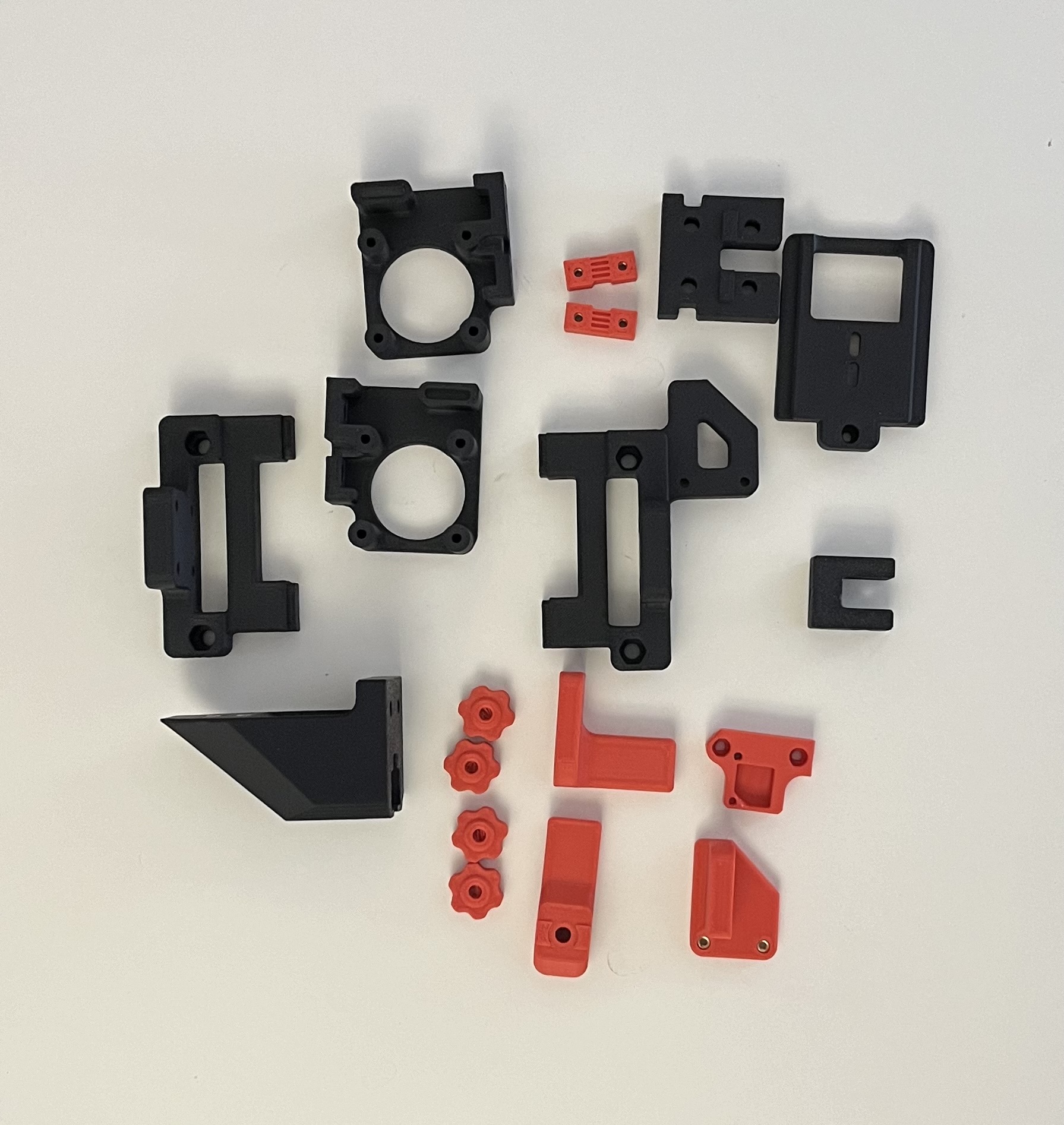
Grills

Hotend
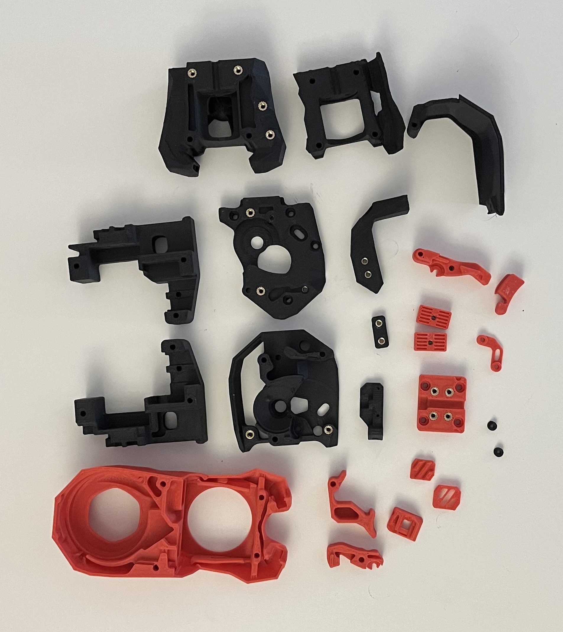
Misc

Panel Mounting

Frame
Assembling the frame went fairly smoothly. I initially used new bolts from the kit, but reused the old bolts since I wouldn’t have enough.
It wasn’t clear in the manual if I needed to modify the left and right sides. After viewing the CAD, I confirmed I had to do both sides.
Z Rails
I cleaned all my linear rails in isopropyl alcohol and used white lithium grease to lube them. I put the worse rails on my Z axis and the best on the X axis.
I also printed alignment tools for the 2040 and 2020 extrusions.
One thing to note was that the manual no longer mentioned T-nuts.
Y Axis
Installing the Y axis linear rails went smoothly.
I skipped the rest of the Y axis as I wasn’t sure which motor to use.
I intially extracted the Y axis motor from my Aquila, but the pulley was permanently attached. There was a similar issue with the X axis motor. I extracted the extruder motor and moved on.
I assembled the bed assembly, endstop, and idler.
Deviations from the manual:
- For the bed assembly, I used M3x6 FHCS screws instead of the M3x8 SHCS for the cable chain (page 23)
- For the Y endstop, i used M5x10 BHCS to connect the cable chain to the extrusion (page 24)
- For the Y axis idler, I used M5 shims instead of the M3 (page 27)
Skirts
I couldn’t assemble the entire front or rear skirts as I didn’t print the middle pieces. My screws for the display also weren’t catching so I skipped it.
I installed the skirts I did have since I didn’t want the printer to be tilted.
Deviations from the manual:
- For the connecting the skirts, I used M3x10 SHCS instead of the M3x8 SHCS (page 32)
- For the mains inlet, I used M3x10 SHCS instead of the M3x8 SHCS (page 36)
XZ Axis
Similar to before, I skipped the Z and X motor instructions.
I assemled everything else except the belts.
Deviations from the manual:
- For the X extrusion, I used M5x10 BHCS and M3x16 SHCS (page 46)
Toolhead (Stealhburner)
I followed the Stealthburner assembly manual.
I chose the Bi-Metalic head break and CHT nozzle since I plan to print in ABS.
Assembly went well until I installed the cable cover. The toolhead PCB wouldn’t allow for the door to close.
I stopped on page 60 as I didn’t want to complete belting until I did the belts for the Y axis.
Deviations from the manual:
- The Siboor manual didn’t mention the heat set insert (page 11) for the set screw
- The Siboor manual didn’t mention to push some heat set inserts below the surface (page 12)
- Didn’t install LEDs as I didn’t have translucent diffuser (page 47)
Day 2 Photos


Day 3 (January 2, 2024)
Y Axis
Using the extruder motor, I attached the pulley and assembled the parts.
I noticed that when attaching the motor and Y axis idler, the panels didn’t line up with the parts. The Aquila seems to have a slightly different holes compared to the Ender 3 V2. I ended up using 2 more M5 T-nuts and M5x30 BHCS bolts to fix the extrusion so that the parts lined up.
My bed also didn’t align with the mounting holes, so I printed this carriage instead.
The manual also called for 1600mm of belt, but that was way too long. I used a PTFE tube to feed the belt through the extrusion. Due to cutting 1600mm of belt, I was short for the rest of the project.
Feeding the Belt
Deviations from the manual:
- Used two M5 T-nuts and M3x30 BHCS bolts to align Y extrusion (page 14, 26, 28)
- Printed different carraige mount for bed
XZ Axis
When assembling the motor mounts, I ended up running out of M3x30 SHCS screws and ended up using my own. Due to cutting the belt short earlier, I also needed to use extras I had.
I noticed that using the pulley gaps from the manual resulted in the belts being crooked. I also tried the measurements from the official Switchwire manual, but it didn’t solve the issue. I ended up adjusting the pulleys until the belts were straight.
Deviations from the manual:
- The Siboor manual didn’t mention the heat set insert (page 39, 41) for the tensioners
- Pulleys set at different positons (page 39, 41)
Day 3 Photos


Day 4 (January 3, 2024)
Y Axis
With the new carriage, I was able to mount the old bed to the carriage. I had to remove the old strain relief by removing a zip tie and prying off the plastic.
XZ Axis
I removed the belts from the XZ axis and cut them to the same length. I reran them and tensioned them using the tensioners near the motors.
Toolhead (Stealthburner)
I attached the Stealthburner to the X carriage along with the wiring. The vertical cable chain didn’t specify how many links, so I counted from the image and got 20 pieces.
Electronics
I assembled and mounted the Raspberry Pi, power supply, 24V converter, and the Klipper expander board. I couldn’t mount the old motherboard as I didn’t have the mount.
I also ran out of M5 T-nuts and started using the M5 post-install T-nuts. The post-install T-nuts were actually easier to work with since they didn’t slide around.
I used the Flashforge motherboard pinout for wiring instead of the manual, as the Aquila was slightly different.
I made my own extrusion cover and mainboard mount.
Deviations from the manual:
- Used M3x16 BHCS with an M3 nut instead of M3x12 SHCS for the screen as they wouldn’t catch (page 33)
- Used custom board mount for mainboard and cover for extrusion (page 72)
- Wires for Raspberry Pi were dupont connectors, used Wagos to add spade connectors (page 77)
- Wires for toolhead (24V) were spade connectors, redid them with ferrules (page 79)
- Used Aquila motherboard wiring instead of Ender 3 motherboard (page 79, 80)
- Used Z end stop wire and motor wire for Y motor since they were shorter (page 80)
- Added finger guard to prevent accidental shocks
- Used cable tie down mount to organize cables
Wiring

Panel Mounting
Mounting the panels went smoothly.
First Power Up
After starting up the printer, I immediately saw a little fire ball. The source was the Klipper expander board. I accidently reversed the polarity, and that seemed to have caused it to ignite.
Klipper Aftermath

Day 5 (January 7, 2024)
Electronics
I rewired my electronics as it was very crammed at the back. I modified the Raspberry Pi mount
Wiring

Flashing Firmware
When I started up the printer, lights turned on and nothing caught on fire this time.
I flashed Mainsail onto an SD card with the Wi-Fi information. After starting up the printer, I was able to update all the software through the Mainsail GUI.
To flash the mainboard, I SSH’d in and ran cd ~/klipper then make menuconfig. I set the config to the following:

After exiting and saving, I ran make. I ran cp ~/klipper/out/klipper.bin ~/printer_data/config/ to copy it to the Config folder and downloaded it via the Mainsail GUI.
I created a folder called Firmware on an SD card and copied the klipper.bin file inside. I did this on a Windows 10 PC just in case.
After inserting the SD card into the mainboard, I turned on the printer and left it for a few minutes to flash.
Day 6 (April 11, 2024)
Software Configuration
I used Ether-3D’s Enderwire 4.2.2 config as the pins seemed very similar to my previous Aquila Klipper config. I made some modifications to my config throughout testing including:
- Including
mainsail.cfgrather thanfluidd.cfg - Changing sensors to
Generic 3950 - Uncommenting
pidfor extruder and heater bed - Changing serial of the mcu
- Uncommenting
z_offset
I decided to do the Klipper screen later.
Initial Startup
Verify Temperature
Both thermistors reported reasonable temperatures.
Verify Heaters
I tested the heaters with a target of 50 Celsius. Only the bed heater heated correctly, the extruder didn’t change. I needed to review the heater_pin
Stepper Motor Check
I used STEPPER_BUZZ STEPPER= to verify stepper_x, stepper_y, stepper_z, and extruder. I noticed that x only moved the left motor and z only moved the right. The y motor moved fine. The extruder motor moved, but there was a grinding sound.
Endstop Check
When I ran QUERY_ENDSTOPS, the X and Y endstops were open while the Z was triggered. I decided to continue with the XY homing and debug the probe later.
XY Homing Check
I verified that the EMERGENCY STOP button worked and began testing.
I ran G28 X and the X axis moved in the right direction. The endstop for the Siboor instructions were on the opposite side of the toolhead, so I had to stop the homing. I changed position_endstop under stepper_x to 0 to fix the homing.
G28 Y homed the bed fine and the endstops worked.
Day 7 (December 21, 2024)
Rewiring
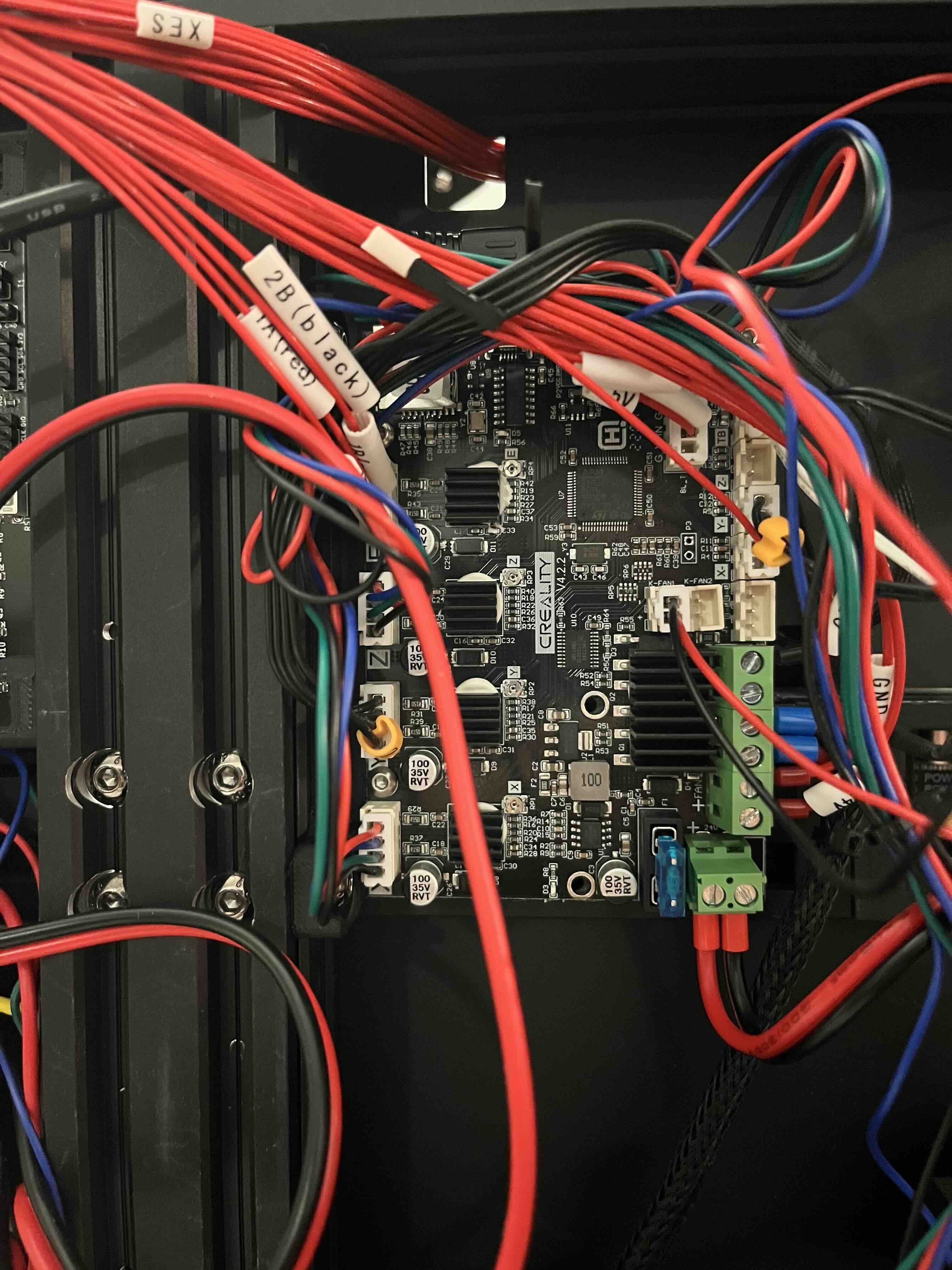
The lack of documentation for the Aquila board halted progress on this project for a while. I acquired some Enders for parts, one of which had a V4.2.2 main board. There is much more documentation about this board in general for Klipper, so I decided to swap it in.
I created a new mount since the mainboards had different mounting points. I used this Reddit post as reference for dimensions and hole points. The layouts were pretty similar, so I just transferred the wires while double checking the Siboor manual.
Flashing Firmware
I referenced some of this video while flashing. I SSH’d into my Pi, then ran the following commands:
cd ~/klipper

make menuconfig
I left the config to the default, which was the same as the first five lines on this GitHub gist:
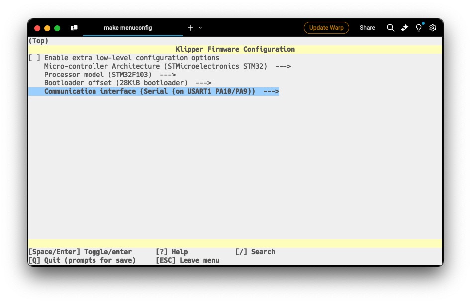
After exiting (Q) and saving (Y), I ran make.
I ran cp ~/klipper/out/klipper.bin ~/printer_data/config/ to copy it to the Config folder and downloaded it via the Mainsail GUI.
I flashed my MicroSD card similar to my Aquila with FAT32 as the file system and the allocation size as 4096 bytes on Windows 10.
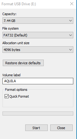
I copied the klipper.bin onto the root of a micro SD card and renamed the file to bigdipper231414.bin. Some others on Reddit noted that if its named the same as a previous flash, it might not work, so I did a random string.
After inserting the SD card into the mainboard, I turned on the printer and left it for a few minutes to flash.
I checked Mainsail a few minutes later, and saw the MCU in the Machine settings page.

I turned off the printer again to remove the MicroSD card before reworking my software.
Software Configuration
Since my printer.cfg was already based on a V4.2.2, I briefly reviewed it before testing.
The X and Y motors managed to home properly, and both the bed and hotend seemed to heat properly. I noticed that my part cooling fan and hotend fan weren’t spinning. After reviewing the wiring diagram, I noticed that they were connected to the Klipper Expander board, which I hadn’t flashed yet.
Flashing Klipper Expander Board
I followed the flashing guide for the expander board.
First, I unplugged all USB devices from the Raspberry Pi except the expander board.
I connected the boot jumper using a jumper from my SKR Pico and reset the board using the white reset button.
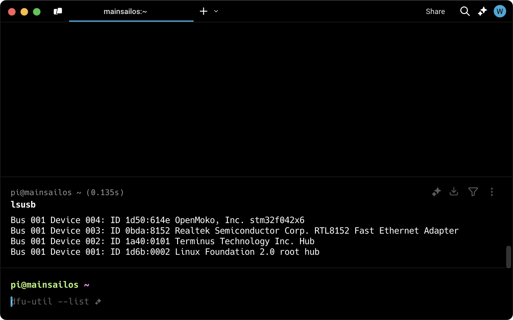
I SSH’d into the Pi and ran lsusb
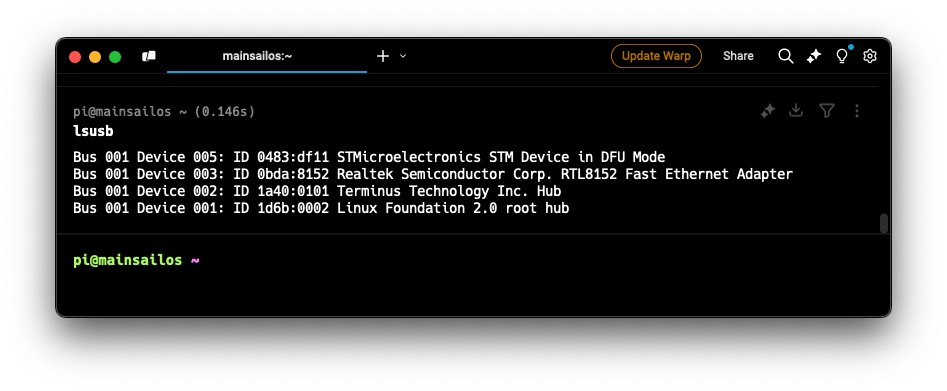
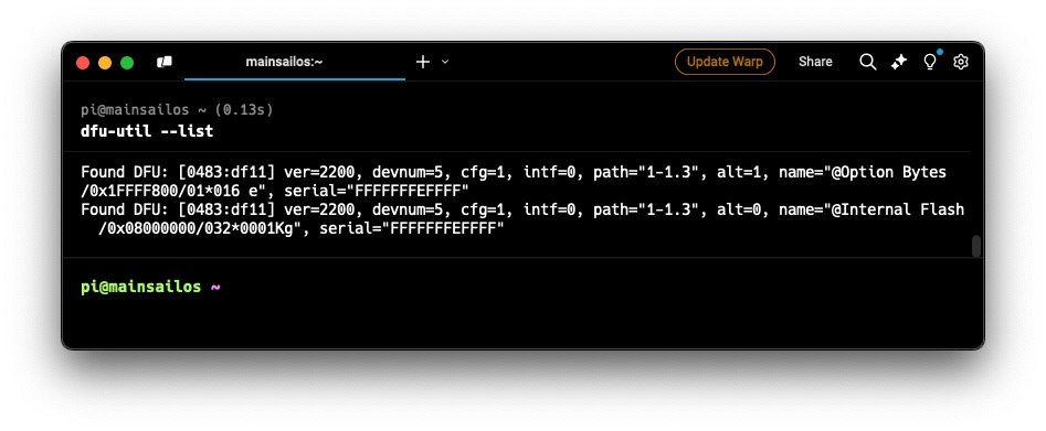
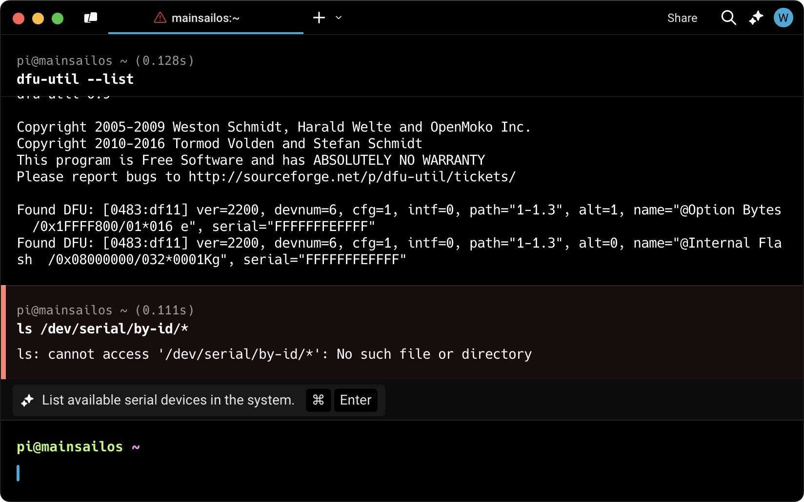
I ran dfu-util --list and noted the text in the brackets [0483:df11]
I then ran cd ~/klipper and then make menuconfig with the following config settings:
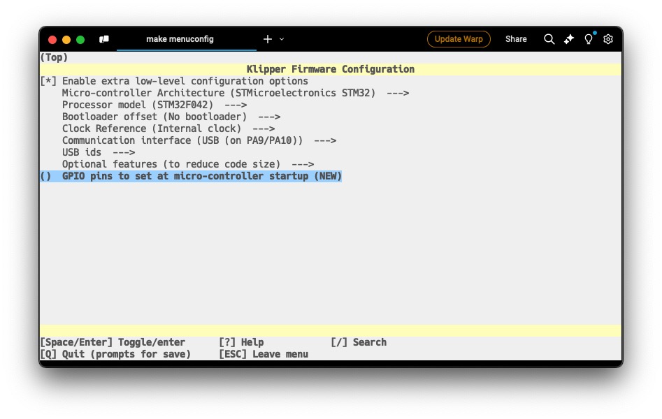
In the Optional features (to reduce code size)
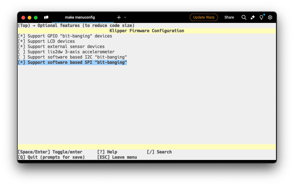
After exiting (Q) and saving (Y), I ran make clean
I then ran make flash FLASH_DEVICE=xxxx:yyyy with 0483:df11 replacing the xxxx:yyyy.
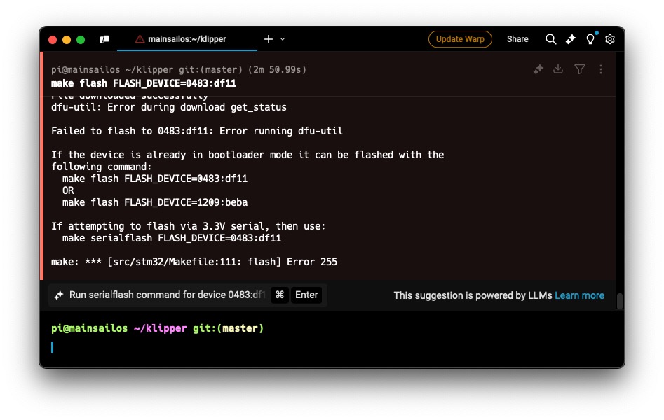
I encountered an error, but it seemed that it was fine. I removed the boot jumper and pressed the reset button.
After running ls /dev/serial/by-id/* I got the serial port name for the Klipper Expander board.
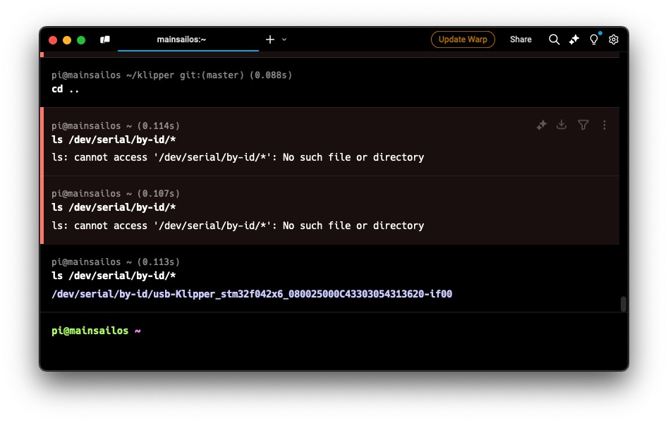
Software Configuration Part 2
I continued down the initial startup list and verified that the all the heaters and the fans worked.
I verified the X, Y, and Z motors move, but my Z probe was too far from the bed. It did trigger if metal was close to it, but the hotend would crash before the probe triggered. The metal needed to be pretty close for the probe to trigger.
I searched a bit on the Voron Discord, and someone else had a similar issue due to having the wrong hotend mount for the hotend. The Siboor V6 hotend should use the dragon mount, but I’ll double check the next day.
Day 8 (December 31, 2024)
Software Configuration
I examined my probe, and noticed that the X-endstop wires were preventing the probe from lowering. After removing the probe and rearranging the wires, I was able to lower the probe further. The probe was now close enough to be triggered when running QUERY_PROBE.
Despite the probe triggering correctly, the hotend still crashed into the bed when homing. After searching around the Voron Discord, it seemed I needed to flip the pin from PB0 to ^PB0.
[probe]
speed: 10
##      If your probe is NO instead of NC, add change pin to !z:P1.24
pin: ^PB0
After making this change, the printer was able to home properly in all directions.
The probe accuracy was somewhat unstable. It would be perfect one time and shift in other tests. I decided to proceed with other tuning and noted it down if there were any problems later.
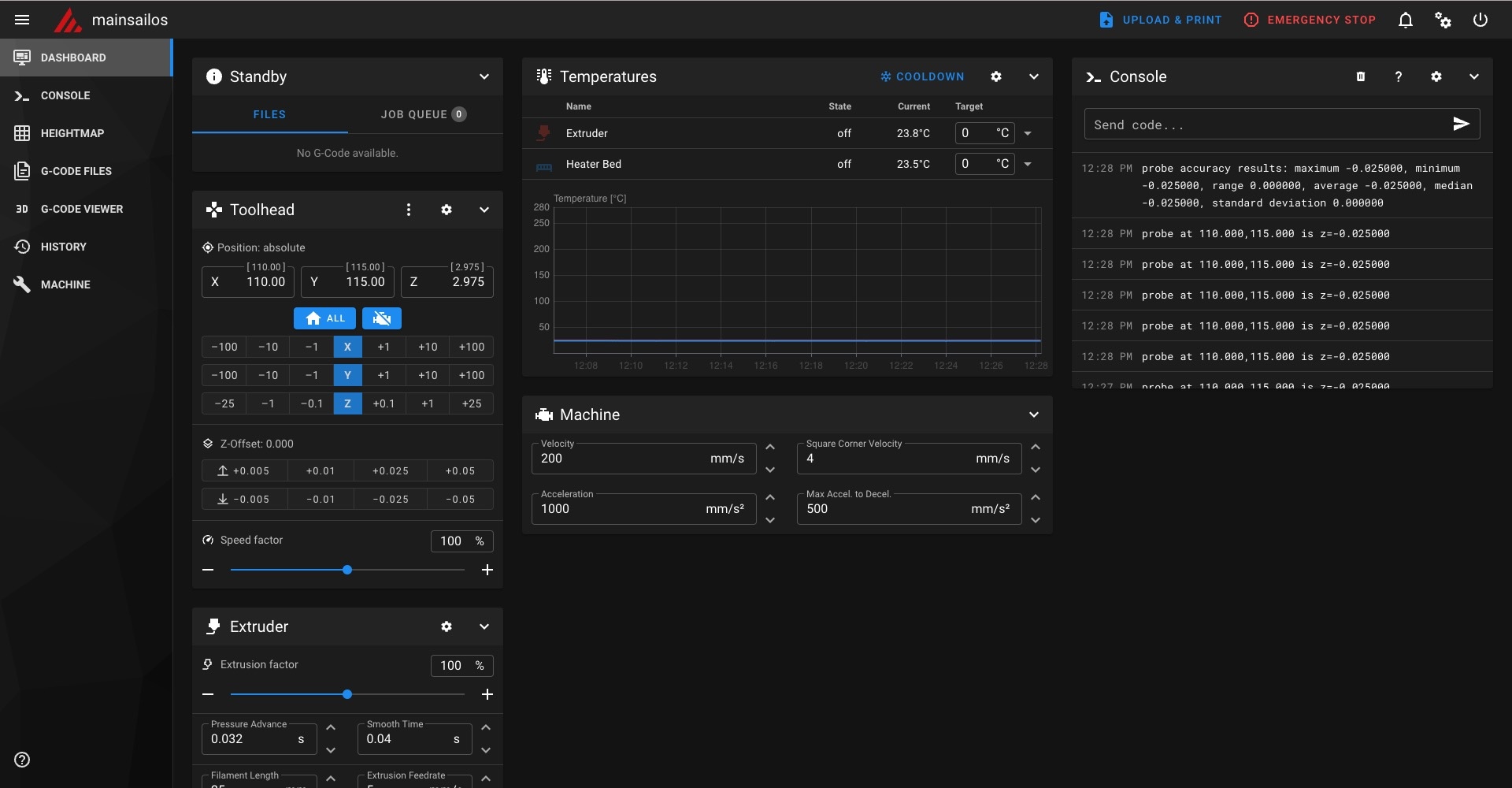
For bed leveling, I didn’t see any instructions, so I adjusted the screw positions in the printer.cfg and ran SCREWS_TILT_CALCULATE. After the probe completed all four corners, it provided some adjustments.
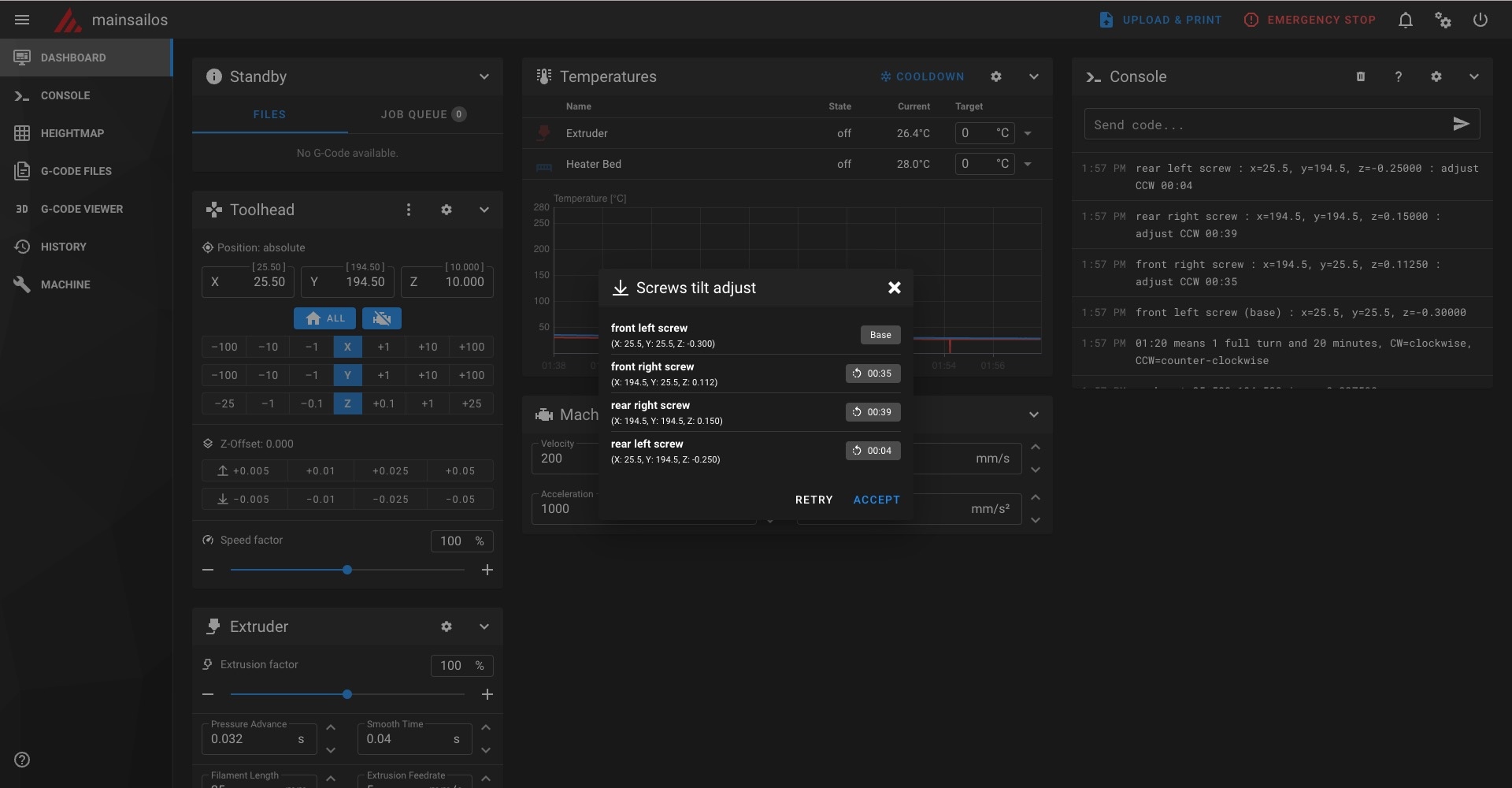
I then realized, since I had spacers, there was no way for me to adjust the bed. I then moved onto adjusting my Z-offset. Since the printer cooled down, I set my extruder to 245C and bed to 100C and let it wait for 15 minutes.
After 15 minutes, I ran G28 to home and BED_MESH_CLEAR to clear any stored meshes. I then ran PROBE_CALIBRATE.
Extruder Motor
I noticed that STEPPER_BUZZ STEPPER=extruder didn’t do anything. It was strange since with the Aquila board, it seemed function, albiet grinding. After rechecking the wiring diagram and continuity, I noticed that the wire labels were incorrect and the pins were switched around.
I removed the wires from the connector towards the controller board, and checked the continuity between the hotend board and wires. I rearranged the wires to ensure that the motor wires aligned with the connector diagram for board wiring (black to black, red to red, etc.). After this rewiring, the motor buzzed during testing.
Extruder Calibration (e-steps)
I tried feeding filament through the extruder, but the direction was reversed, so I switched the [extruder] dir_pin directiony by adding a ! in front of the pin name. After fixing this, I noticed the filament got caught and didn’t make it out of the hotend. I tore down the hotend and reassembled it before retesting.
Day 9 (January 1, 2025)
Hotend Fixes
I noticed that the filament kept getting caught in the hotend, despite me recutting the PTFE tube.
I removed the nozzle and saw a clear path between the nozzle and top of the PTFE tube. After further disassembly, I noticed that there was a gap in the hotend between the heat break and the top of the heat sink. The PTFE tube was supposed to extend further into the hotend than I thought. I remeasured the amount of tubing I needed, and found that I needed 43mm as indicated below.
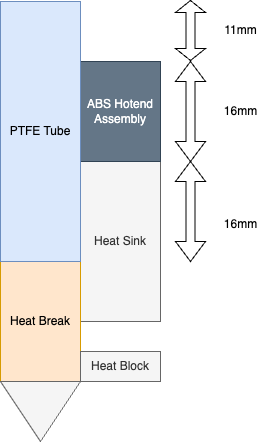
After reassembling the hotend, I hot tightened the nozzle and redid my PID tune. After doing the PID tune, I redid my Z-offset as the heat break shifted a bit with reassembly. The filament successfully extruded filament, and I configured my e-steps.
Printing
For my Slicer, I used OrcaSlicer V2.2.0. I added the default Switchwire configuration and modified the print settings to the PIF recommendation and the build volume to the numbers in the printer.cfg. I began printing the spool holders as I was using my V0.1 to hold the spool.
Further Configuration
I followed this guide to enable exclude object. I also adjusted my printer.cfg to enable the bed mesh. I used this macro to replace my PRINT_START macro.
I then printed the remaining parts for the printer.
I noticed that I would get Unknown command:"M106" which was likely due to my part cooling fan being mapped wrong.
I two macros to my printer.cfg and M106 S255 and M107 work properly that override M106 and M107.
Day 10 (January 2, 2025)
Klipper Display
I had yet to set up the klipper display, so I followed the guide by Voron. My Fysetc display was a V2.1 without the R1 & R4 components, so I didn’t need to modify it.
I used the configruation from the GitHub.
The firmware flashing was exactly like the klipper expander board, and even the firmware compliation settings were the same. I made sure to unplug all the other USB devices before doing this so I didn’t flash the wrong device.
After flashing and adding the serial path to my klipper-mini12864.cfg, I got this error Option 'spi_bus' is not valid in section 'display'. After searching through the Voron and Siboor Discord, I couldn’t find a solution. I commented out that portion and some other options that also caused that error. After asking GPT, it recommended to check that I didn’t reference [display] in any other sections. I noticed that my printer.cfg also had a [display] declaration, and commented it out.
In theory, everything should have been configured. I had to edit the kill_pin as it would immediately trigger. After a few seconds, the mcu would disconnect and the display never lit up. I looked through the Discords again, and the only mention of a similar problem had no solution. The Fysetc display might’ve been dead. I decided to order a new display and module (to convert the EXP1 & EXP2 to USB C) as I wasn’t sure which component didn’t work. I purchased a Fysetc replacement, but if that didn’t work, I’d order a BigTreeTech display instead.
Day 11 (January 3, 2025)
Finishing Touches
All that’s left for the printer was the extensions for the sides and the middle grills. After printing them out, I inserted the heat set inserts and assembled the parts. It was tricky to get all the parts in place as a few of the electronics got in the way. I ended up needing to use M3x16 SHCS for the display instead of M3x12 as the bolt didn’t go far enough to catch the insert.
After assembling everything, I noticed that my doors wouldn’t close and would hit the display knob. The door panels should be flush with the top of the printer. I removed the hinges and reattached them, using the top and bottom magnet to ensure they were aligned. I also just removed the display as I would need to replace it anyway.
The final touch were the feet and bottom panel. Since I ran out of M5x30 bolts, I used M5x40 until my order arrived. It still works as it just prevents the feet from falling off.
With that, the Switchwire is done other than replacing a few bolts and the Klipper screen. I do need to do some tuning and slicer configuration, but the overall build is complete.
Day 12 (January 14, 2025)
Display
My bolts and replacement Klipper screen showed up much faster from AliExpress than I thought. I removed the display and reused the module converting the EXP pins to USB C as the new one was USB Micro-B.
I followed the same steps as before, but I didn’t encounter any differences. The MCU path was the same and the display still wouldn’t light up. I tried switching USB ports and the module to the USB Micro-B version.
After swapping to the other module, I noticed that after running lsusb, the device already different than before.
I connected the boot pins and reset the board to set it to DFU mode. The numbers I needed from the DFU were the same, 0483:df11, but I knew that there wasn’t Klipper installed due to ls /dev/serial/by-id/* not working.
I used the same configuration options as before:
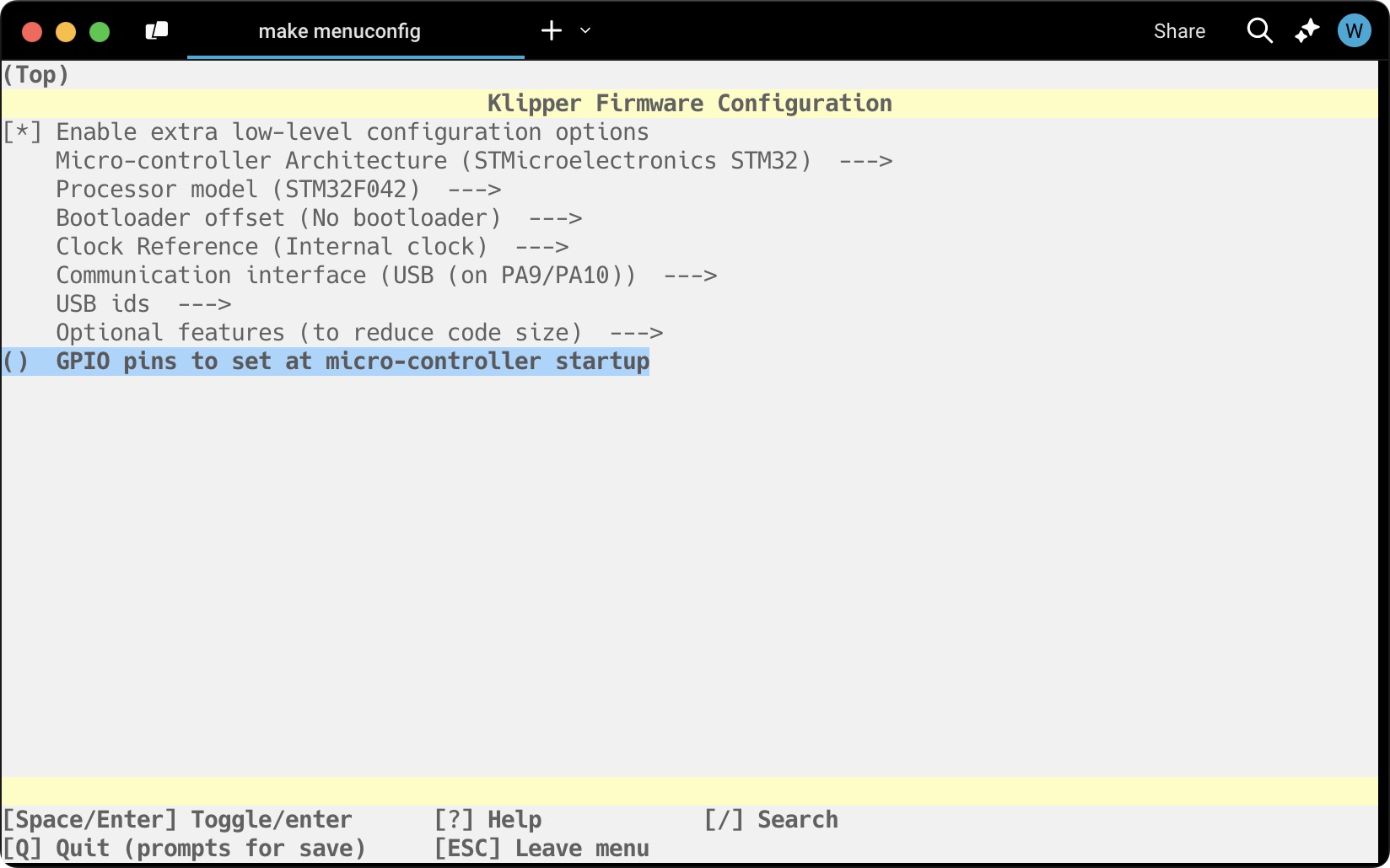
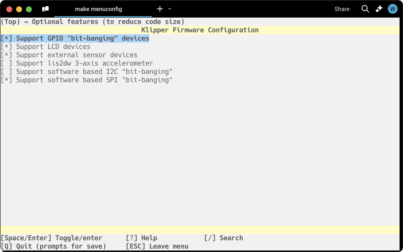
After running the make flash FLASH_DEVICE=0483:df11, I got the same error as usual.
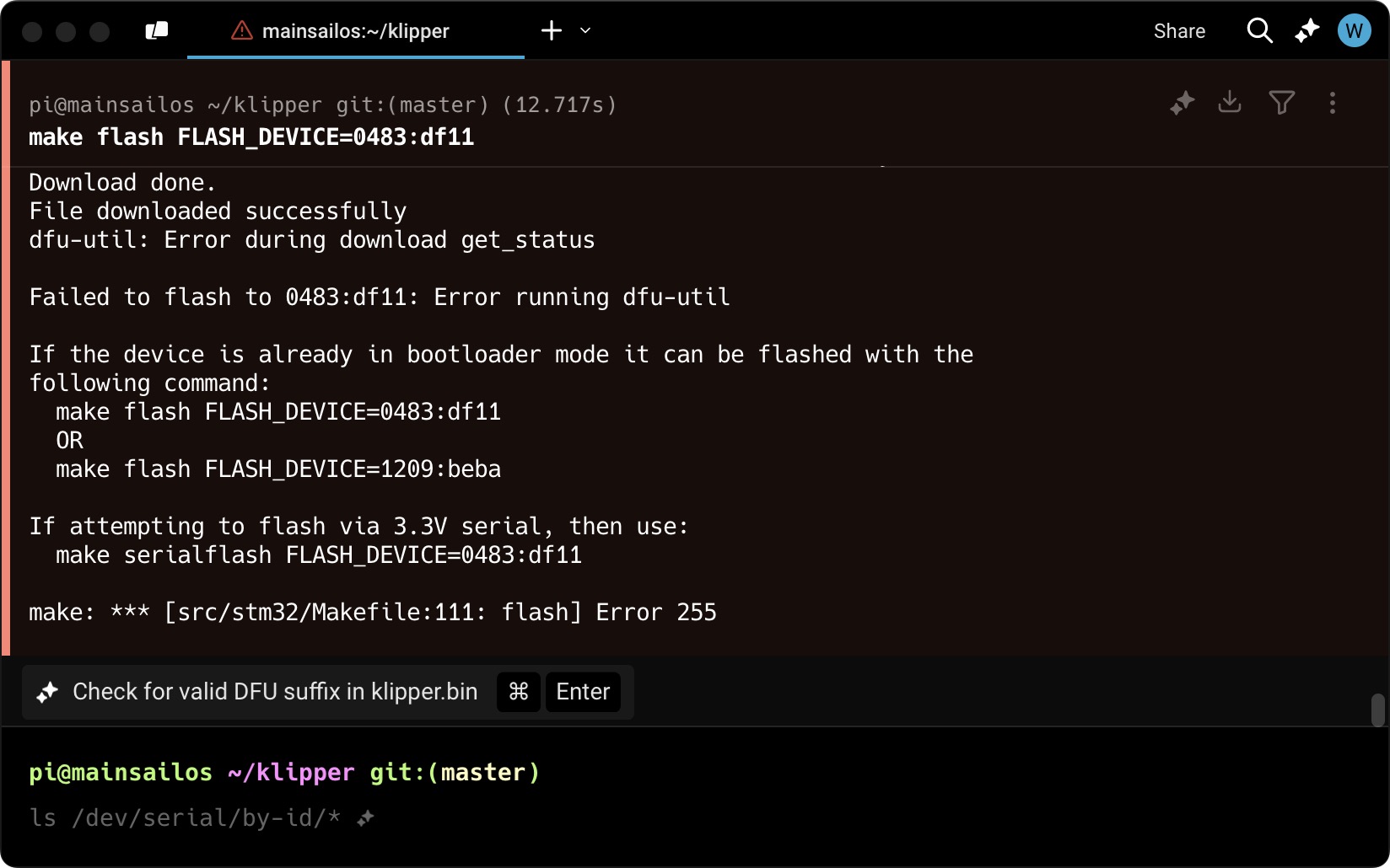
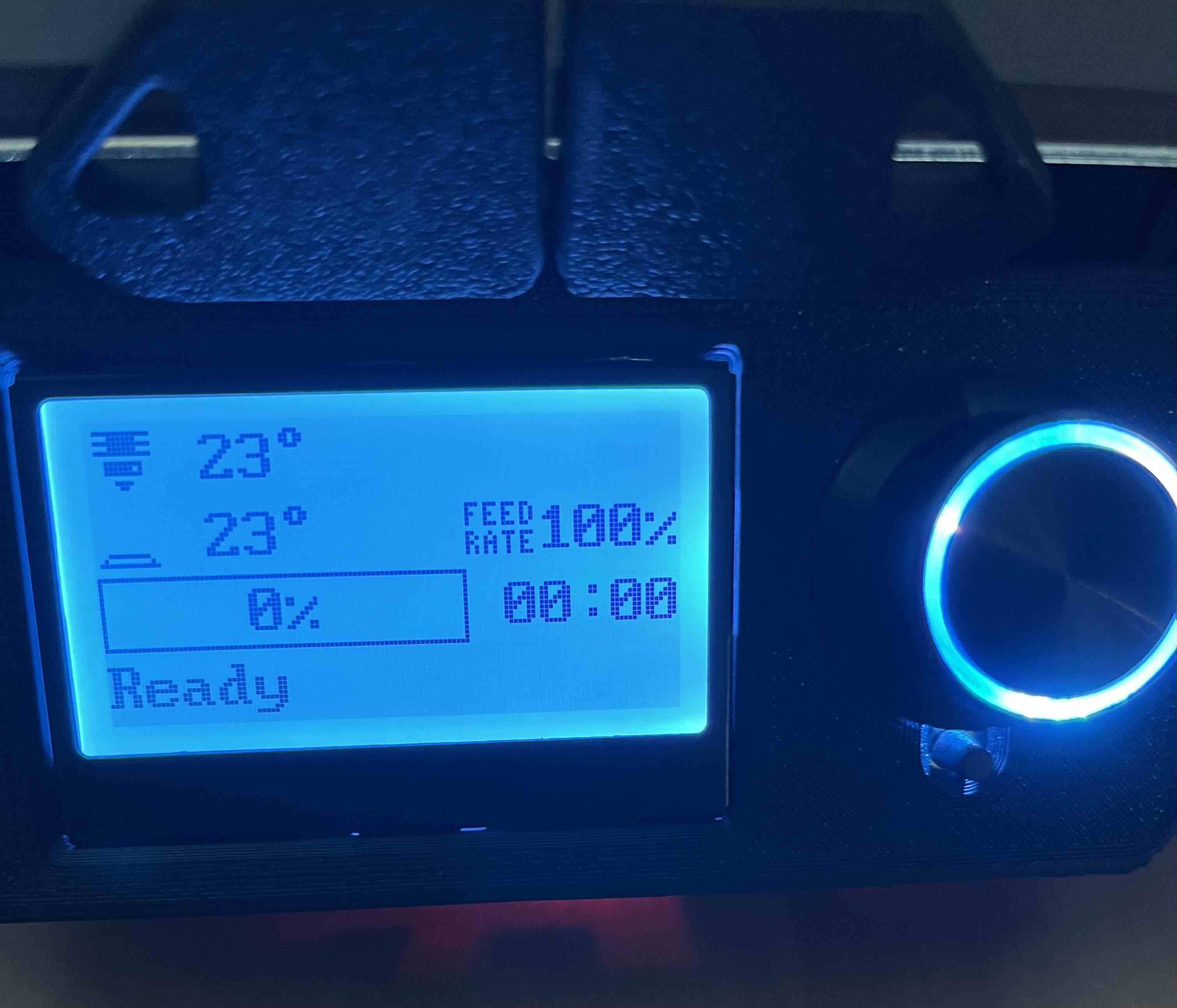
I removed the boot jumper and clicked the reset button a few times. I was able to confirm that the MCU number was different and reassembled everything. After connecting all the USB devices and adding the display’s MCU path, the display lit up and I was able to control the printer.

The only problem left was that the kill switch didn’t function, and when I flipped it using ^, it immediately triggered and didn’t let the printer start. I’ll need to figure out how to get it working before tuning.
Day 13 (August 26, 2025)
0,0 Point
I realized I never finished configuring my printer after encountering some mishaps while printing my F-Zero parts.
While going through the Voron Manual again, I don’t believe I checked my 0,0 point. My 0,0 seemed to be more than 5mm too far into the bed, however I couldn’t adjust it any further as it was already hitting my endstops. I did notice that the printer couldn’t fully travel in each direction. I tested the limits for each axis and adjusted the position_max for each axis. The X and Y axis seemed to only be 5mm while Z was reduced by 30mm.
E-Steps
I already did my PID tunes for the bed and hotend, but never did my e-steps. I used this calculator when recalculating my rotation_distance. It seemed that I was overextruding a lot and it could explain why I was encountering problems while printing.
Conclusion
Overall, it was a very worthwhile project. Having the larger format printer enables me to print larger parts and gives me confidence to tackle other mods.