Day 1 (August 23, 2025) - Day 6 (August 28, 2025)
I decided to use my Switchwire to print the parts as it had a larger print volume.
Originally was planning to use richardjm's Mgn9h x-rail, but after looking through Discord, the Pandora gantry was recommended. I still wanted to go extrusionless, so I did some searching and discovered zruncho's vampire_bat on Reddit. This allowed for an extrusionless gantry while having a front facing linear rail (which was more flexible for probes apparently). I didn't want to deal with pins as I didn't have them and didn't want to deal with drilling. I decided to use the Micron Pandora mount instead.
The parts weren't the prettiest, but they seemed functional. Once I swapped from my Black eSun ABS+ to my Firefighter Red eSun ABS+, I encountered problems with clogging. I reviewed my build post for my Switchwire and realized I never adjusted my e-steps. I swapped my filament to Red eSun ABS+ and was able to get two prints out of the Switchwire, but the final print kept clogging. I noticed gaps in the parts it printed. For the final remaining parts (skirts), I decided to swap back to my V0.1. This reminded me how convenient the LCD display on my Switchwire and V0.2 was, but the V0.1 was my most reliable printer.
By the end of the 28th, I had all the parts printed (and some extras) along with the reprints using my V0.1 for any especially bad parts.

Day 7 (December 14, 2025)
I realized I was missing some parts:
- Baseplate panel
- Panels if going BoxZero
- Screws to attach the 100mm and 200mm extrusion to make a singular 300mm extrusion
I was going to source the panels from Amazon later and get them cut at my local makerspace.
I ordered 16mm M3 grub screws to connect the two extrusions together.
I also changed my Wifi network, so I created a wpa_supplicant.conf file based on the Mainsail documentation. The section provided in the documentation didn't work for me, so I used the example that was already on the Pi's SD card.
Provided sample:
# Simple configuration for a typical WPA2 network

ctrl_interface=DIR=/var/run/wpa_supplicant GROUP=netdev
update_config=1
country=US # US Country code

network={
  scan_ssid=1
  ssid="<Name of your wireless LAN>"
  psk="<Password for your wireless LAN>"
  proto=RSN
  key_mgmt=WPA-PSK
  pairwise=CCMP
  auth_alg=OPEN
}
I disassembled the V0.2 to it's bare parts. I found a hex screwdriver much easier to use than the hex keys I used to assemble the printer.
I also noticed one of the belts was very worn down.

Day 8 (December 15, 2025)
Frame
I decided to build the outer frame first as it would visually be most impressive.
I combined the 100 mm extrusions from the top hat with 200 mm extrusions. It doesn't seem to matter which extrusions are used due to the frame corners. There are no blind joints to owrry about.

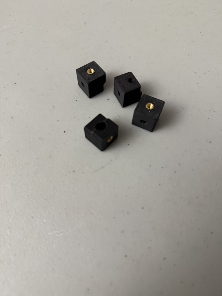
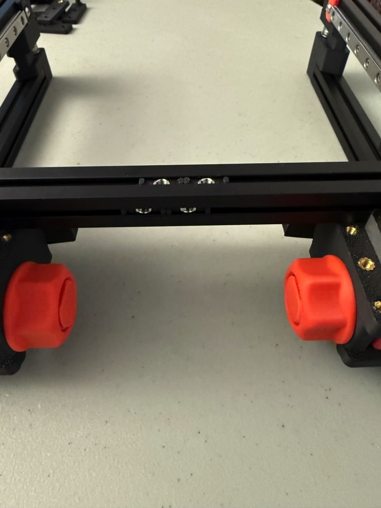
I used the CAD to figure out which corner went where. I used M3x8 to attach the extrusion ends to the corner pieces. I used M3x6 screws for additional holes in the corner pieces to reinforce the corners. I used NoDropNuts (NDNs) for all the additional holes except the four that had a protrusion to line up with the extrusions (shown below). I used regular M3 nuts to connect these four.

With that, the frame was complete. I didn't add any additional NDNs as I wasn't fully sure how many I'd need where, and it is pretty easy to remove a corner.

Screws used:
- 24 x M3x8 BHCS (extrusion ends to corners)
- 16 x M3x6 BHCS (additional reinforcement)
- 16 x M3 nuts (additional reinforcement)
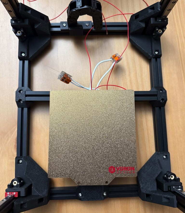
Bed
The bed seemed like the next easiest part to complete. I assembled it based on the instructions and the CAD.
I ended up using M3x10 BHCS for the three outer pieces (to connect the bed to the frame). The M3x8 screws were too short. I didn't add the bed itself as I needed to remove the screws from the old assembly. I left 3 NDNs for the spacers later on. I had to get the 100mm extrusions from the leftover parts of my V0.1 (since the V0.2 came with a Kirigami bed).
Screws used:
- 8 x M3x8 BHCS (centre piece to extrusions)
- 11 x M3 nuts (spacers and centre piece)
- 3 x M3x10 BHCS (connect the three)
- 1 x M3x16 grub screw (to connect the two 100mm extrusions)


More Drop Nuts
I wanted to work on the linear rails next, but realized that I needed to add the M2 Nut adapters. I figured I might as well add more NDNs that I could find out from the CAD. I added the four Nut adapters to the vertical axis and place the remaining two in a 200 mm extrusion for the gantry.
Screws used:
- 4 x NDNs (rail stops)
- 4 x NDNs (idlers)
- 6 x NDNs (bed)
- 2 x NDNs (cable chain)
- 4 x M3 nuts (door magnet)
Linear Rails
I soaked all my linear rails in rubbing alcohol and moved them around to clean out the old grease.
After they dried, I sprayed WD-40 White Lithium Grease and moved the carriages around to ensure the ball bearings were lubricated.
I had a total of 7 linear rails to install. Two of them I bought afterwards. I would put the two best linear rails on the flying gantry as it matters the most. The remaining four would be for the vertical Z axis.
I had the following rails:
- 1 x MGN9H 200mm (for Vampire Bat gantry)
- 1 x MGN7H 150mm (from AliExpress)
- 5 x MGN7H 150mm (from original Siboor kit)
I added rail stops to prevent the carriages from falling off once I installed the rails.s
- 4 x M3x8 BHCS (rail stops)
Heat Set Inserts
I added the follwing heat set inserts:
- 4 x Top hat
- 4 x Idler
- 8 x Enclosure
- 4 x Z drive mounting
- 4 x Vampire Bat gantry
Z Linear Rails
I installed the linear rails one at a time on each of the corners. I used the MGN7 rail guide to ensure the rails were centred before tightening. Once installed, I moved the rail stops to the end of the linear rail to prevent the carriage from falling.
Screws used:
- 40 x M2x6 SHCS

Vampire Bat Gantry
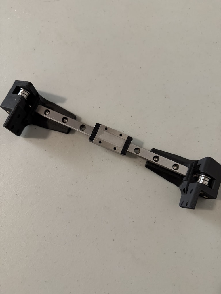
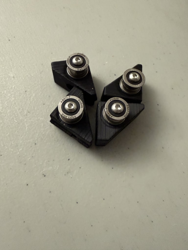
The Vampire Bat gantry was pretty easy to install. Since I was only doing the Bat XY Joints, I only four bearings and screws. The M3x30 screws seemed a bit too long, but the M3x25 barely caught the heat set insert. I decided to keep the M3x30 and screwed it until it reached the bottom of the heat set insert.
Parts used:
- 8 x M3x30 BHCS
- 8 x F623 bearings
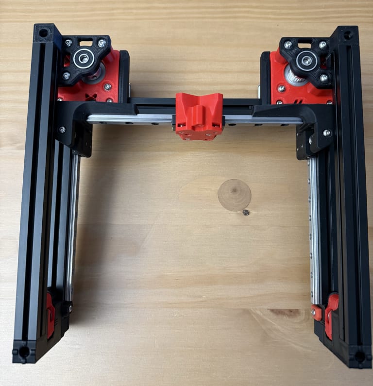
Flying Gantry
It seemed that the F-Zero reused a lot of the gantry from the V0 including the motor mounts. I had to replace two of the top frame extrusions to get the right extrusions with holes for two blind joints. I mostly followed the assembly of the V0.2 for the X Axis, A/B Idlers, and A/B Drives.
One differences were the idler ends which replaced the direct screws into the extrusions.
The V0.2 only had 5 rail stops (one stop was the Z endstop). I temporarily used a spacer in place of the stop while I print another rail stop. I used NDNs everywhere except for the A/B idlers. The screws were too close to the end of the extrusion, so I just used regular M3 nuts. I noticed that my GT2 20T Pulley on one of my motors was much lower than it was supposed to, which could've explained the increased belt wear I had. I redid the measurements and added loctite.
A/B Drives (same as V0.2) Parts used:
- 12 x M3 shims
- 12 x F623 bearings
- 2 printed spacers (from V0.2)
- 16 x M3x35 BHCS
- 4 x M3x30 BHCS
- 8 x M3 washers
- 6 x NDNs (to attach drives to extrusions)
A/B Idlers Parts used:
- 4 x M3x35 BHCS
- 4 x F623 bearings
- 4 x M3 shims
- 2 x M3 nuts (to attach to extrusion, no NDNs as didn't fit)
Rails: Parts used:
- 20 x M2x6 SHCS
- 2 x NDNs (for rail stop)
- 1 x M3x8 BHCS (rail stop)
- 1 x M3x12 BHCS (temp rail stop)
Everything else: Parts used:
- 4 x Heat set inserts (idler ends)
- 6 x M3x8 BHCS (to connect idlers and drives to extrusion)
- 2 x M3x10 BHCS (to connect idlers and drives to extrusion, followed V0 manual for this length)
- 8 x M2x6 FHCS (to connect the Vampire Bat to the rails)


Z-Drives
The Z-Drives looked pretty complicated at first glance. After exploring the CAD, it didn't look too bad. It did require a lot of heat set inserts for all the gearbox assemblies.

On the 50mm long shafts (5mm diameter), I placed then in the following order:
- 625 bearing
- 60t GT2 pulley
- 16t GT pulley
- 625 bearing

I noticed that when trying to close the gearbox with an M3x35 BHCS, the gearbox wouldn't fully close. It seemed that my bearing was too big or my print was too small. I decided to try this another day while I figured out why the pair was so far off.

Parts used:
- 36 x Heat set inserts (8 per drive assembly plus 1 for each gearbox bottom)
Z Idlers
These were pretty easy to create. I placed one M3 washer then two F623 bearings like any regular idler.
Unfortunately, the idlers have a similar issue as the frame corners. There is a protrusion to help guide the idler, but this leads to conflicting with the NDNs. I decided to not install the idlers until later.
Parts used:
- 2 x M3 washers (between bearing and plastic)
- 4 x F623 bearings
- 2 x M3x20 BHCS
Day 9 (December 17, 2025)
Vampire Bat Gantry
Printed new rail stops while I was reprinting Z-Drives
Rails: Parts used:
- 1 x M3x8 BHCS (replacement rail stop) Removed:
- 1 x M3x12 BHCS (temp rail stop)
Z-Drives
I compared my Z-Drives to the CAD and other people's completed builds. I noticed that my bearings didn't seem to fully sit in the print, while others had the outer part of the bearing partially covered by the plastic. I confirmed this by pressing the bearings into the printed parts and noticed that it didn't seat all the way.
There were a few potential reasons to this including the Z seam being positioned in the bearing holder. I decided to increase the bearing slot on the part in CAD and reprint rather than file it down or the print at 102% size. This would make it easier to replicate in the future and wouldn't cause the rest of the print to be slightly larger than needed.
I opened up the CAD in Autodesk Fusion and tinkered around with different methods. I initially thought about using the existing bearing object and combining it with the printed part as a hole, but it wouldn't match on the other side and may not have enough play. I ended up using the Push/Pull tool to extend the existing hole. To determine the amount of room to add, I used a caliper on the bearing and zeroed it. I kept increasing the caliper until it felt like there was enough play but not too much. I ended up with 4mm of extra room (2mm felt too small and 5mm felt like too much).

After adjusting the holes on the two parts, I exported them to a .step file and did a test print. I uploaded my step files to GitHub.
I purchased some Polymaker ASA on sale for Black Friday and used to to print the replacement Z-Drives. I used the default OrcaSlicer for Voron Generic ASA and changed the temperatures:
- Nozzle: 255 Celsius
- Bed: 100 Celsius
The bearings ended up seating perfectly with almost no play. The two gearbox parts seems to sit slightly crooked when combined together, but I didn't think it would affect anything.
I proceeded with printing the remaining parts. To print the mirrored gearboxes, I just manually mirrored the objects in OrcaSlicer before printing. I ensured that the orientation was the same as the original STL (with the large flat side down).
Day 10 (December 18, 2025)
Z-Drives
With all the Z-Drive gearboxes printed I verified that all the bearings fit then proceeded with adding all the heat set inserts again. Since I printed the ASA with higher temperatures, I used 270 celsius on my Pinecil while inserting the inserts.
After all the inserts were inserted, I align all the pulleys so that they matched. I made sure I added the 200mm closed belt as I wouldn't be able to afterwards. I decided against adding the open belt now as I didn't want to accidentally cut a belt too short and waste belts. Something to note was that both the gearbox and motor used 16t pulleys, my 60t GT2 pulleys came with 20t pulleys so I stored the 20t pulleys.

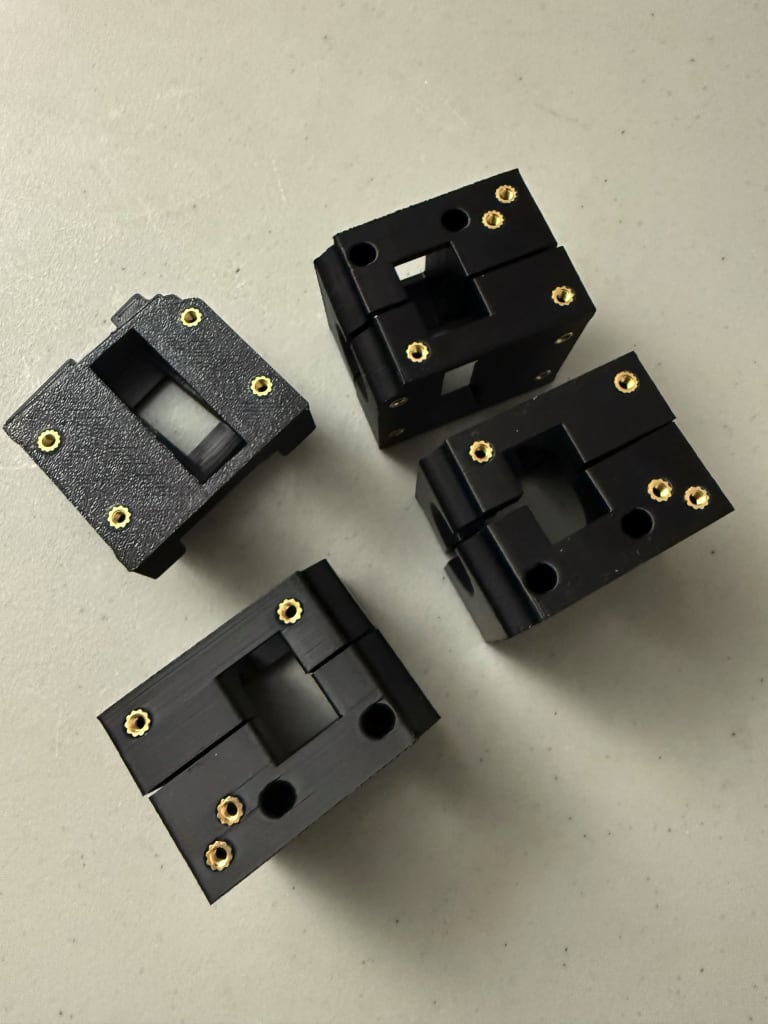
The gearbox assembly was the most strenuous part of the assembly so far. Initially I just tried screwing all four M3 screws until they reached the insert, but ended up with a large gap and screws that were stuck. I found that it was easier to screw all four screws into the outer half (the part with only two heat set inserts) first. After the ends of the screws reached the bottom of the outer half, I sandwiched the two parts together and screwed while applying downward force to ensure there was no gap. After screwing in all four corners a bit, the parts sticked together and I could finish the assembly without needing to hold the parts together. It was a lot of repetitive screwing for the gearboxes.
For the NEMA17 motors, I faced all the connectors on the opposite side of the printed part that connects to the frame. I chose this to give as much space as possible for wiring. I ordered these parts over 2 years ago, so I don't remember any specific reason for the motors I picked.
I didn't add threadlock to any of the pulleys as I wasn't sure if they were at the final positions. I left the Z-Drives unattached from the frame as I had yet to get and install the base plate.
Parts used:
- 32 x Heat set inserts (8 per drive assembly)
- 4 x 60t GT2 5mm-bore pulley
- 8 x 16t GT2 pulley (four for the motor and four for the gearbox shaft)
- 4 x 50mm x 5mm shafts
- 4 x 200mm GT2 closed belts
- 8 x 625 bearings
- 4 x NEMA17 Motors
- 12 x M3x12 BHCS (motor mounts)

Day 11 (December 19, 2025)
Heat Sets
I added heat set inserts to the wire organizer, x-carriage, and the z joint gantry attachments.
Parts used:
- 10 x Heat set inserts
- 4 x for x-carriage
- 4 x for z joint gantry attachments
- 2 x for wire organizer
- 2 x M3 Nuts (for x-carriage)
Z-Gantry
I was going to attach the Z-Gantry to the rails, but realized that my M2x10 BHCS had a head smaller than my 1.5mm hex key. It was the only M2 screw that didn't use that key, and I didn't have anything small enough for it.
More NDNs
I decided to attach the Z-idlers, so I added more NDNs and the magnetic latch while I was at it.
Parts used:
- 8 x M3x8 BHCS
- 4 x for magnetic latch
- 4 x for attach Z-idlers to frame
- 28 NDNs
- 8 x for Z motors
- 4 x for Z-Drive gearbox mounting to frame
- 16 x for skirts, 4 each side
- 4 x M3 Nuts (for idlers)
- 4 x 6x3mm magnets (for magnetic latch)
Removed:
- 4 x NDNs (previously for idlers)

Gantry
After reviewing the CAD, I noticed that I was missing some more nuts for the wire organizer and Klicky Probe. I also added a NDN for a potential Y-endstop. I also assembled and attached the wire organizer.
I considered adding more NDNs to the top of the X-axis extrusion, but only added one for the Y-endstop. I might change to the Tulip gantry in the future, and the CAD didn't require any more NDNs on that axis.
Parts used:
- 5 x NDNs
- 1 x for Y-endstop (top of extrusion)
- 2 x for wire organizer (rear of extrusion)
- 2 x for Klicky Probe mount (bottom of extrusion)
- 4 x M3x8 BHCS (2 for organizer to motor mount, 2 for lid of organizer)
- 2 x M3x6 BHCS (organizer to frame)
- 1 x PG7 Cable Gland

Bed
To add the bed to the frame, I removed the three existing M3x40 screws and M3 nuts from the bed. To remove these screws, I peeled back the magnetic base enough to unscrew, then smoothed it down once I was done. I used M3x20 BHCS and the 12mm spacers before fully screwing it into the bed frame. I have spare magnetic bases if this one ends up failing, but I will leave the stock one until a problem arises.
Parts used:
- 3 x M3x20 BHCS
- 3 x M3x10 BHCS
- 8 x M3x8 BHCS
- 9 x NDNs

Klicky Probe NG
I decided to use the Klicky Probe NG as the probe seems to be one of the most popular options.
After printing all the required parts:
- KlickyNG_Probe_Dock.stl
- KlickyNG_Probe_insert_3mm.stl
- KlickyNG_Probe_body.stl
- KlickyNG_ABSB_mount_base.stl
- KlickyNG_ABSB_mount_front.stl
I also found the optional helpers very useful:
I assembled as per the instructions. The photos weren't always the clearest, but I found the exploded view of the probe helpful for orienting the steps.
I ended up trimming the two outer legs of my Omron D2F-5 switch as they were too long and prevented the swtich from sitting further into the mount. I also decided to superglue the three exposed magnets in the probe assembly as they had a lot of play and kept falling out.
The probe overall wasn't too difficult to assemble, but the magnets made it frustrating at times.
Parts used:
- 1 x Omron D2F-5 switch
- 30 cm of 20 AWG wire
- 5 x M2x10mm self-tapping screws
- 8 x 6x3mm magnets

Day 12 (December 20, 2025)
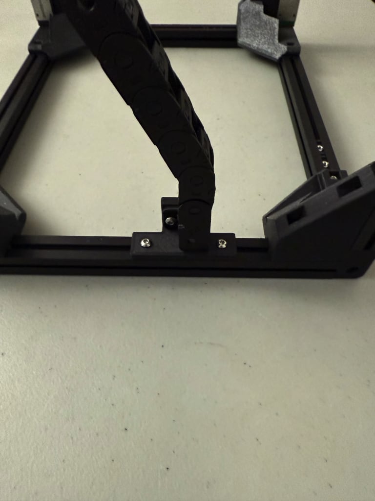
Cable Chain
The cable chain mounts from the CAD didn't fit the cable chains I had for the V0 (7mm x 7mm) nor the Switchwire (10mm x 11mm). I looked around online for the Micro Panzer that was used in the CAD, but only found the PanzerChain 2.4. I decided to export the chain links from the CAD and print them.
After printing the chains, I noticed that the chains didn't link nor move smoothly. Compared to the injection moulded AliExpress cable chains, these were way more rough. I decided to buy more 10mm x 11mm cable chains from AliExpress and use those and mod the printed parts to attach the chain later. I picked these cable chains as they are semi-enclosed and the ability to open the cable chain makes things much easier. Since I have the Nitehawk 36, I would also need to route the larger single cable through (likely along with the Y-endstop).
I also printed the angled bracket from the CAD to attach to the other side of the cable chain.
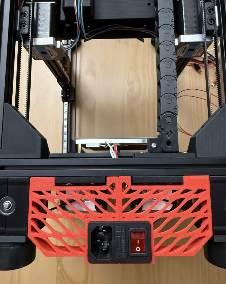
Base Plate
The existing base plate didn't have any holes for the wires. Those on the DoomCube Discord seemed to drill holes after printing the baseplate, but since I was laser cutting my sheet, I decided to add holes myself. I added a 30mm diameter semi-circle hole near where the rear cables would be placed. I also added a 12mm diameter hole slightly above the mounting hole for the power supply. I chose 12mm based on the existing grommet STL I had printed. If the holes ended up too large, I could print a grommet or cover.
Files:
Day 13 (December 21, 2025)
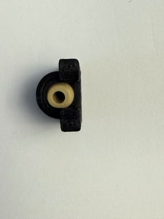
Z-Axis Mount
The KGLM-03 bearing on my mount seemed to protrude beyond the print. This collides with the rail mount and didn't seem expected. Others on the DoomCube Discord also had this same problem.

I opened up Fusion and increased the depth of the bearing channel on the part 0.4mm.

After printing the part, the bearing fit snuggly with no play.
Files:
Day 14 (December 22, 2025)
Cable Chain
I decided to do another attempt to modify the Micro Panzer to fit the 10x11 cable chain that I ordered. I needed to increase the width of the anchor.
First, I used the split body tool to split the anchor into two pieces.

The distance between the two pieces was 10.845mm.

I needed slightly less than 14mm for my chain to fit, so I moved the body up 3mm.

I then used the push/pull tool to connect the two bodies together.

I increased the hold width slightly, and printed the prototype to see how it fit. The pieces were a bit tight, so I did some more modifications.
I decreased the depth of the part that connects to the chain.

I further increased the hole width.
After another print, the parts fit snuggly.
Heat Sets
I did the heat set inserts for the Klicky Probe mount and the cable chain.

I then connected the Klicky probe dock to the mount and the cable chain to the frame.

Parts used:
- 2 x M3x16 BHCS (Klicky Probe mount)
- 4 x M3x8 BHCS (Cable chain)
- 4 x Heat set inserts
Files:
Day 15 (December 23, 2025)
Toolhead
I initially planned to use the Mini-AfterSherpa with the Sherpa Mini Extruder. They were easy to service and I really liked that the extruder was separate from the rest of the toolhead.
There are Klicky Probe mounts for the V0, but the dock is mounted near the front extrusions. The Z attachment points interfere with this location and moving the Klicky Probe mount further in would result in lost Y axis distance.
Meningitix created a cowling and mount for a different variation of the Klicky probe, but due to the lack of familiarity with this Klicky mount, I decided against it.
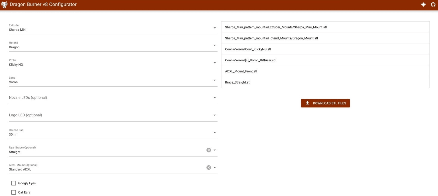
I decided to look outside of using the Mini-AfterSherpa and discovered the Dragon Burner v8. Others seemed to enjoy it online and ModBot praised it in his video. The Dragon Burner supports many hotends and extruders including the Sherpa Mini. It also seemed to have native support for the Klicky NG.
I used the provided configurator to determine what STLs I needed. I wasn't against purchasing more parts as I already needed to wait for some parts I ordered (including pins for the Vampire Bat and possibly Tulip gantry).
For some reason, I had clogging issues with two of my eSUN ABS+ rolls (Red & Fire Engine Red). I manually unclogged both multiple times, but it would keep clogging mid print. After switching back to my Polymaker ASA, the clogs stopped.
Gantry
Since I ordered pins, I decided to print the X carriage and belt clips from the Vampire Bat.
Day 16 (December 24, 2025)
Probe
I watched The Next Layer's Voron mods video and discovered the Voron TAP. There were some issues with using the TAP including needing additional hardware (PCB and MGN-9H carriage). I could source these from AliExpress, but it would cost at least $40 for the kits. I could build a lot more Klicky Probes with this amount. I was a bit hesitant to use the Klicky as the magnetic alignment and continuity on my probe seemed a bit off.
I looked through Reddit threads and people suggested the Beacon probe. This was even more costly than TAP, but while looking into the Beacon I discovered the BTT Eddy. It seemed to be an almost drop in replacement for the Omron probe in other Voron printers. It is also much cheaper than the Beacon or TAP at around $25 each for the probe. After watching YGK3D's and ModBot's videos, I decided to go with the Eddy.
I would be using the eddy-ng repository. The Eddy didn't seem to natively supported by the Dragon Burner, which makes sense as the Omron probe would take a significant amount of space in a V0 and probing isn't really needed on the V0 bed. Bryon James created a brace for the Dragon Burner which replaced the support brace with a mount for the Eddy.
Vampire Bat Gantry X-Carriage
Aluminum tubes from AliExpress are quite expenive due to the shipping costs. I found a tube at my local Sayal for $3.95 CAD. The tube has an outer diameter of 5/32 (~3.97mm) and an inner diameter measures at around 3.25mm. Since the belts will be pulling from both sides, I think the additional play will be negligible. The exact model of the tube I got was from K&S Precision Metals with the SKU 8103
I didn't have a reamer, so I used my Wera 118068 2054 Hex Screwdriver to gradually increase the size of the two vertical holes until an M3 pin easily slide. The screwdriver shaft is around 3.03mm in diameter.

For the aluminum tubes, I ended up filing them down until they were around 14.6mm in length. Everything slid in pretty smoothly, but the belt clips that held the tube were a bit loose. The current holes in the CAD were 4.5mm in diameter. I used the timeline in Fusion to find when the diameter for the hole was created. It turned out to be the first sketch. While editing the sketch, I saw that the diameter of the hole was actually a parameter (hole_dia), so I changed it to 4.05 and then saved the sketch.

After confirming the new radius was 2.025mm (half of the diameter), I exported the file as a .step.
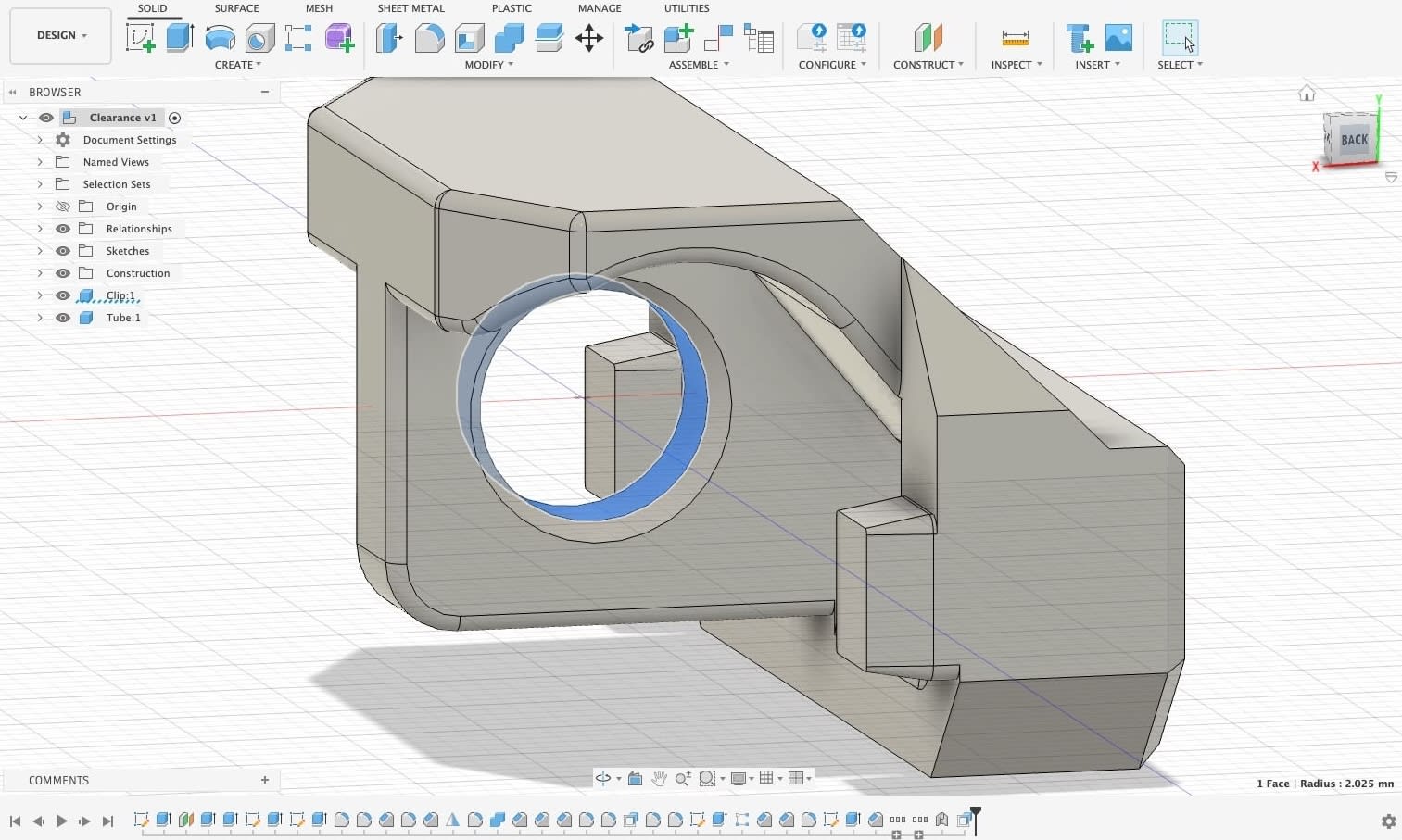
My 40mm pins were still on order, so I used 20mm pins to test.

I added the two M3 nuts near the top of the x-carriage to attach the toolhead. I also added the two M3x30mm BHCS from the buttom of the carriage to help stiffen the carriage.
Parts used:
- 2 x M3x30 BHCS (for carriage stiffening)
- 2 x M3 nuts (for toolhead mounting)
- 2 x 15mm Aluminum tubes (4mm OD, 3.25mm ID)
Files:
Heat Sets
I inserted the heat set inserts for the x-carriage and the Dragon Burner toolhead.
Parts used:
- 8 x M3 heat set inserts
- 2 x for x-carriage
- 4 x for cowling (the README only shows two, but in Oct 2023, additional inserts were added to the ducts)
- 2 x for Sherpa Mini dragon hotend mount
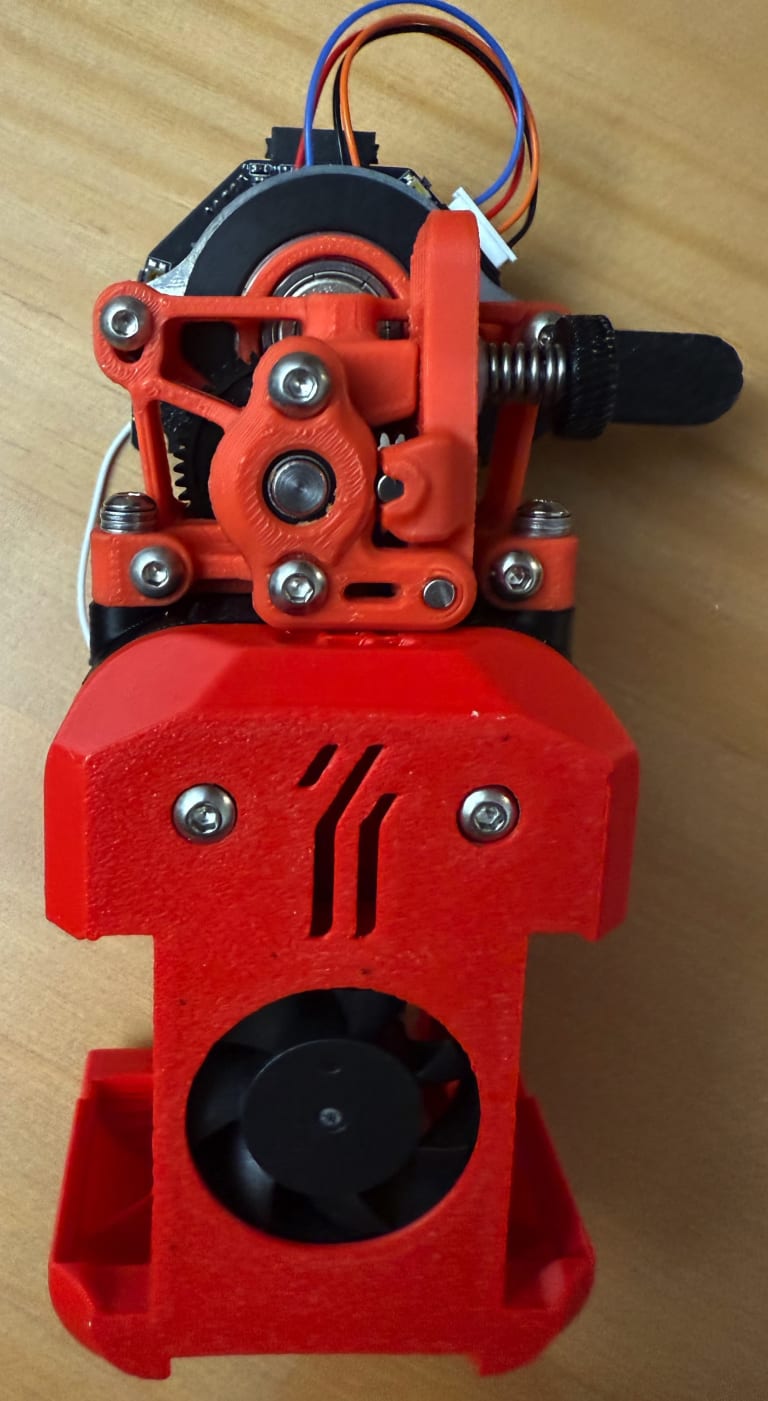
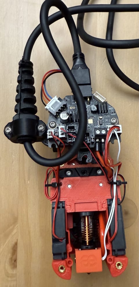
Toolhead
I decided to assemble the toolhead with the parts I had. I was just missing the two 4010 blower fans, so I could proceed with the rest of the toolhead.
First I slid in the 3010 hotend fan into the cowl. There was a hole on the side that I was able to route the fan cable through.
Then, I attached the dragon hotend to the Dragon_Mount.stl. I reused the two M2x6 BHCS that were used for the Mini-AfterSherpa.
For the PTFE tube between the Sherpa Mini and hotend heatsink, I decided to use some Capricorn Tubing I had leftover. I measured the distance from the top of the Sherpa_Mini_Mount.stl to the heatsink (25mm) and from the bottom of the Sherpa Mini to the gears (8.28mm). I cut 33.28mm of tubing and placed it into the dragon mount.
I then slid on the Sherpa Mini mount and screwed in two M3x20 BHCS to attach it to the cowling.
I finally slid on the Sherpa Mini extruder and attached it using two M3x20 BHCS.
I pushed some 1.75mm filament through the filament path to verify it was able to go all the way to the nozzle.
With that, the toolhead assembly was done other than the blower fans and the brace. I needed to print the brace with for the Eddy mount.
Parts used:
- 2 x M2x6 BHCS for attaching Dragon heatsink to Dragon_Mount.stl
- 1 x M3 nut for Sherpa_Mini_Mount.stl
- 4 x M3x20 BHCS
- 2 x for attaching Sherpa_Mini_Mount.stl to cowl
- 2 x for attaching Sherpa Mini extruder to toolhead
- 33.28mm of Capricorn Tube for filament path between Sherpa Mini and hotend heatsink


Day 17 (December 25, 2025)
Printing Parts
I printed some parts:
- Sharkfin_DB_NHK-V1 for Nitehawk strain relief
- usb_adapter_mount.stl for holding Nitehawk USB adapter
- Eddy Loop + Straight V1 to mount Eddy
- Eddy Loop V1 to mount Eddy (as backup in case there is a clearance issue)
- Vampire bat clips
I was also planning on converting to a Crucible, and noticed that I might need one of the 100mm extrusions for the bed. The F-Zero bed with Zerofilter only requires one 200mm extrusion and the parts below.
I decided to reprint the following parts in ASA as I wasn't entirely sure about the eSUN ABS+ with the bed temperatures:
I also purchased some an M3 standoff kit with 12mm standoffs to replace the bed spacers as plastic touching the bed directly was not ideal.
I really liked the wago mount for the Kirigami bed, so I wanted one for the F-Zero's bed. Luckily, there was an existing Fusion file, so I could reference the measurements while adapting it.
I used the skills I learned from an Autodesk tutorial. It was really fun modelling the mount and it ended up fitting perfectly on my first print (which wasn't surprising as it was the same dimensions).

Since my adjusted Vampire bat clips were too tight, I adjusted the hole diameter to 4.25mm and reprinted it.

After the reprint, the aluminum tubes fit snuggly.
Files:

Day 18 (Dec 29, 2025)
Gantry
My pins from AliExpress arrived, so I tested out the fit on the Vampire Bat. After some more reaming, the pins slid smoothly and fell out with gravity alone. When attaching the clips, I noticed a lot more resistance. It seemed that the tubes still had too much play and would misalign when the clips were inserted into the carriage. I tried reducing the clip hole diameter to 4.00 mm but the tolerance was too tight and the resistance was much worse. I decided to stick with the existing clips I had and use something like another pin or a screwdriver to align whenever I attach the clips.
With my new pins and 16T Solid Idler, I started printing the parts for the Tulip Gantry. I figured I might as well do it now rather than disassembling the gantry and possibly redoing the belts later. I ended up printing all the parts in the Live Folder except for:
- STLs/LIVE TULIP/Live XY joints/MMU XY Upper Part (optional)
- STLs/LIVE TULIP/Live Idler tensioners/Live Lazy Cam Tension Idlers (optional)
- STLs/LIVE TULIP/Umbilicals (optional).
I also got a set of new Wera screwdrivers so I can attach the Z-gantry using the Hex 1.3 driver and my M2x10 BHCS.
Day 19 (Dec 30, 2025)
Z-Belts
I decided to cut my Z-belts and test out the length. As per the assembly manual, I cut 700mm of belt as I had a box top rather than the V0.1 top hat. After cutting one belt, I routed the belt through the Z-drives and did a test fit to confirm the length. After confirming the length was alright, I cut the other three belts. I can't actually assemble the Z-drives until I have the baseplate.
Toolhead
I started stripping the wires needed for the Nitehawk toolboard. The thermistor and hotend fan required JST PH 2.0 connectors. I followed IOT Expert's guide for how to crimp the wires. The wires were too thin for my wire stripper that went down to 22 AWG. I ended up carefully stripping by rotating the sharp cutting end of my wire stripper until I got off the insulation. I ended up using the 1.3mm section to crimp rather than the 1.6mm. My hotend fan only had two pins, so I connected the positive and negative terminals and had no pin for the tachometer.
The hotend cartidge required ferrules, so I just my rachet wire crimper. The wire guage for my hotend cartidge was 20 AWG.
I attempted to attach the Nitehawk toolboard to the Dragon Burner using blaket's V0 mount, but the top right of my toolboard collided with one of the wiring routes. I decided to print iamnotahippie's XOL mount as it used a Sherpa Mini extruder and should work well. I printed the 5.5mm ziptie PUG since the Nitehawk cable was around 5.5mm.
Day 20 (Dec 31, 2025)
Bed
My M3 standoffs arrived, so I decided to reassemble my bed. I disassembled everything down to the bare parts. I used a 200mm extrusion for the two rear attachment points with two NDNs. My standoffs were a bit long, so I used three M3 washers between the standoff and the extrusion. For the front of the bed, I used a heatset insert on the innermost hole. I used M3x10 BHCS on all three bed attachment points. The front attachment point is loose, but when aligning the bed in the frame, it becomes rigid with the other two mounting points.
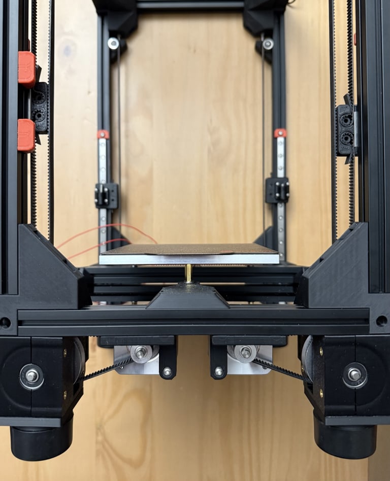
I mounted the bed onto the main frame for now. It doesn't seem to align with the nozzle and is too far close to the front of the printer.
Parts used:
- 2 x NDNs (200mm extrusion)
- 1 x Heat set insert (front bed mount)
- 3 x 12mm standoffs
- 9 x 3x7x0.5 washers
- 3 x M3x10 BHCS (bed to standoffs)
- 6 x M3x8 BHCS (bed to main frame)
Removed:
- 3 x M3x20 BHCS
- 3 x M3x10 BHCS
- 8 x M3x8 BHCS
- 9 x NDNs
Toolhead
My Eddy probe arrived, so I decided to continue assembling the toolhead. After attaching the Eddy probe mount, I noticed that it collided with the Vampire Bat X-carriage. I tried reorienting and attaching the X-carriage first, but the two parts kept colliding.

I also noticed that despite the brace on the back of the toolhead, one side of the cowl bent more than the other due to the heater cartridge.

I disassembled the toolhead and rerouted the wires. I routed the hotend fan and heater cartridge to through the top of the toolhead. I would have moved the thermistor there as well, but couldn't get it out of the Nitehawk.

To solve the clearance issue with the Nitehawk and the Eddy, I created a part in Fusion to use the rear heatset inserts on the cowling behind the fan ducts. I preferred this too over the brace since heatset inserts would be more durable to removals and reinsertions than the bare plastic the brace went into.
I printed the new brace and attached it to the toolhead. It still collided with the Vampire Bat and the Eddy seemed too far back and would hit the X extrusion when pushed all the way back. I decided to print the Pandora X-carriage and redesign the Eddy mount to sit closer to the hotend.
The Pandora carriage worked well and I was able to attach the toolhead to the gantry. While redesigning the Eddy mount, I realized that even if the Eddy was touching the bottom of the MGN9 carriage, it would sit below the nozzle. Since this rear mounting wouldn't work, I decided to convert my model to just a brace that used the heatset inserts.
Parts used:
- 4 x Heat set inserts
- 2 for Nitehawk mount
- 2 for Eddy mount
- 2 x M3x16 BHCS (attach Nitehawk to Sherpa Mini extruder with mount)
Files:
Gantry
I decided to mount the gantry for now to help me gain an understanding of the full movement of the printer. I added one NDN and one M3 nut to each bottom corner of the gantry to attach the Z joint gantry attachment pieces.

I attached the Z attachments using 4 M2x10 BHCS per rail. I also decided to add Wagos to the bed wires so the ends wouldn't rub against anything.
I then flipped over the printer and screwed a M3x16 BHCS from the bottom (normally the top of the printer) up. Once all four corners were in the heatset inserts, I ziptied the gantry so it wouldn't crash into the bed before flipping it over again.

The gantry could now tilt with somewhat limited motion (due to the zip ties).

Parts used:
- 4 NDNs (gantry attachment)
- 4 Nuts (gantry attachment)
- 8 x M3x8 BHCS (gantry attachment)
- 4 x KGLM-03 IGUS Spherical bearing
- 4 x M3x16 BHCS (gantry to rails)
- 16 x M2x10 BHCS (rail attachments)
Possible Eddy Mounts
I considered printing the Switchwire Dragon Burner mount, but it would likely still collide with the AB motors and X extrusion.
To prevent this, I could use the gantry from the Pandora's Box, which removes the X extrusion and the widest part becomes the NEMA 17 motors. If the motors still collided with the probe, I could flip the motors upside down which would free up plenty of space for mounting. This isn't unusual as the Voron 2.4 AWD has the motors flipped as well.
It doesn't seem like mounting the Eddy probe behind the toolhead with the Tulip gantry is possible as the X extrusion seems structural and it would required quite a few of modifications.
Another option is placing the Eddy probe on the front or side of the toolhead. After moving the probe around with the probe on the front, right, and left. The left and right would reduce the X printable area due to the probe preventing the toolhead from going all the way in one directly. The front was possible, but I wasn't sure if it would be able to probe the entire bed.
A possible option would be lowering the Dragon Burner toolhead enough that the Eddy probe would fit where the Eddy probe would sit in the mount I made earlier in Fusion. I would lose some Y printable area, but that's the least limiting axis for me when printing. After inserting the probe's USB cable and placing the probe behind the toolhead, I measured the distance between the bottom of the nozzle and the bottom of the probe. I measured the difference at around 8mm. The Eddy should be 2-3mm above the surface of the bed, so I would need to shift the toolhead down 10mm.
Modified Toolhead
I took the Dragon Burner CAD and modified the cowling and hotend mount to have the hotend sit 10mm lower.

Files:
Day 21 (Jan 1, 2026)
Toolhead
With the modified toolhead printed, I reassembled the toolhead with the new parts. I cut a new length of Capricorn Tube that was 10mm longer than the previous (43.28mm). I had to trim it a little after a test fit, but otherwise the filament slid smoothly.
Transfering the hotend and extruder wasn't too difficult, but I had trouble removing the thermistor's JST connector from the Nitehawk. I ended up breaking off the two thermistor wires and had to redo the crimps. The connector came off after prying it back and forth with tweezers. The connector itself almost came off, but it just pushed back in.
I had add M3 washers to the screw that attached the extruder to the toolhead. The M3x30 BHCS was too short but the M3x35 BHCS was too long. I added five 0.5mm washers to each side.
After the toolhead assembly was complete, I attached the toolhead to the X gantry and did a test fit of the the Eddy probe. The probe fit well, and I detached the toolhead so I can add the part cooling fans when they arrived.
Parts used:
- 2 x M3x35 BHCS
- 10 x M3 washers
- 6 x Heatset inserts
- 43.28mm of Capricorn Tube
Removed:
- 2 x M3x20 BHCS
Tulip Gantry
I disassembled the flying gantry to remove the AB drives and idlers.
I followed the deleted Tulip manual from the GitHub. I added heatset inserts to the AB motor parts.

I then assembled the bearing stacks as per the manual. It was the same as the original V0 bearing stack, just with M3 pins instead of screws. I reused the printed spacers from the AB drives as the hex printed ones did not fit.

I noticed that the holes on all my printed parts were too small for the pins. The CAD and STL had 3.2mm diameter holes, but after printing they were close to 2.5mm in diameter.
I printed LuckyPants' calibration tool and the average error was -0.98%. The average for inner holes was -1.9%, but even with that the 3.2mm hole should not have shrunk so much. One option was to print the external perimeter first rather than inner then outer.
I resliced and reprinted the idlers (as they were the smallest pieces) to see if it was a one-off error. The hole remained small and consistent, so I set X-Y hole compensation under Precision in OrcaSlicer to 0.15mm and reprinted the A idler. The fit was tight, but I was able to get the full idler assembled. I reprinted all the AB driver parts (since they all had holes for the pins).
When assembling, I referenced the CAD. It was very useful since it had all the screws and bearings including the sizes.
Parts used:
- 4 x Heatset inserts
- 4 x M3x30 pins
- 2 x M3x18 pins
- 16 x 3x6x0.5 washers/shims
- 16 x F623 bearings
Front Tensioners
- 4 x M3x10 BHCS (as per manual 2 for top extrusion, 2 for extrusion for bottom extrusion)
- 2 x M3x35 BHCS (for bottom extrusion)
- 2 x M3x12 BHCS (for adjusting idler)
- 4 x M2x10 self-tapping screws (to close idlers)
- 2 x M3 nut (for idler to adjust)
AB Motors
- 6 x M3x30 BHCS (to attach to motor)
- 2 x M3x8 BHCS (to attach to motor)
- 2 x M3x10 BHCS (to attach to extrusion)
- 2 x 625RS bearing (at top of motors)
Removed:
- 4 x 3x6x0.5 washers/shims
- 20 x M3x35 BHCS
- 4 x M3x30 BHCS

Day 22 (Jan 2, 2026)
Tulip Gantry
I attached the AB motors to the gantry. I had to swap two of the rearmost NDNs to M3 nuts as the M3x10 BHCS was too close to the idler end. I had trouble getting that screw in, and removed the idler end to slide the motor in. I noticed that the M3 nut protruded from the extrusion, so I would need to modify the idler end to create a gap for the M3 nut. This protrusion is also shown on the CAD. I modified the idler from the F-Zero CAD to include a gap for the M3 nut.

I used two more M3x12 BHCS to attach the motor mounts to the existing NDNs. One of the gantry attachment pieces also broke when removing the flying gantry, so I printed two more and added the heatset insert before reattaching it. I also reattached the top extrusions using the same M3x10 BHCS that attached it before.
The Vampire Bat x-carriage still seemed to collide with the Eddy probe's cable, so I decided to keep the Pandora x-carriage. I still needed to route the belts, which according to the Voron V0.2r1 manual, is 1 metre for each run (2 metres total).
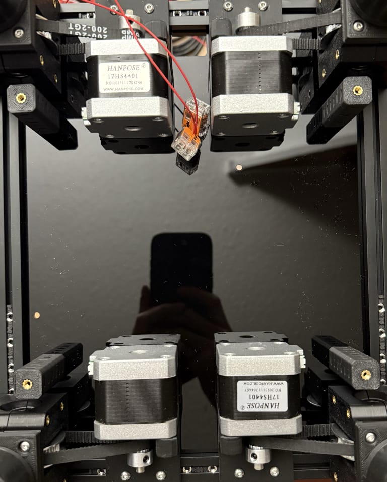
After cutting a metre of belt for each run and aligning the teeth to ensure they are the same length, I ran the belts through the pulleys. After feeding them into the X-carriage, I tightened the belts and double checked the extra belts to ensure they were even. I had my idlers pushed to the very back so I could do the final tightening. I used the Prusa tuning tool to measure frequency by placing my phone in the centre of the gantry and strumming the inner belts (X-carriage pushed all the way to the back). I had troubles with the tool as it would often not detect a strum, or record 50 Hz then 120 Hz. There is a GT2 Belt Tension Meter, but there are no Canadian suppliers so I ordered one from the UK for around 21 USD after taxes and shipping.

Parts used:
- 4 x M3x12 BHCS (attach AB motors to gantry)
- 2 x M3 Nuts (replaced NDNs)
Removed:
- 2 x NDNs
Files:
Day 23 (Jan 4, 2026)
Toolhead
My 4010 blower fans from AliExpress arrived, so I finished up wiring my toolhead. I used the 1.0mm section to crimp which worked much better than the 1.3mm section of my crimper. I found that it was easier to remove everything and install the fans on the cowling first, then attach the hotend mount and extruder mount. I didn't trim the fan cables any shorter than I needed to and looped the wires just in case I needed to recrimp or change toolheads. I ran the cables to the Nitehawk and ziptied everything down.
I did test fit on the X-carriage and couldn't confirm if it would fit as the untrimmed belts prevented me from fully mounting it. My Eddy probe mount also needed to be redesigned as it collided with the blower fans and wouldn't fit. The new fans also seemed to reinfoce the whole toolhead and prevented the bending of the cowling near the nozzle.


Day 24 (Jan 6, 2026)
Panels
I learned some more Autodesk Fusion, so I decided to redo the baseplate drawings and create drawings for the rest of the panels of the F-Zero.
After measuring out the dimensions of the frame, I got the following panel sizes:
- 329mm x 212mm (front and rear panels)
- 261mm x 329mm (side panels)
- 261mm x 212mm (top panel)
After creating the sketches, I exported them to a .dxf file as that's what LightBurn uses. I followed LightBurn's legacy guide to export the DXF. After creating a new sketch, I included the entire project (P) before exporting it. I used ShareCAD to verify that my export worked properly.
For the baseplate, I redid my hole drawings using more constraints.
For all the panels, I added a 2mm radius to the corners as that is what the V0 seemed to have. I might create a bottom panel later on for the very bottom after the build is complete.
Files:
- Deck Panel
- Baseplate
- Front and Rear Panels
- Side Panels
- Top Panels
Eddy Probe
I also redesigned the Eddy probe so it wouldn't collide with the part cooling fans.
Files:
Day 25 (Jan 8, 2026)
Tulip Gantry
My redesigned idler ends with gaps for M3 nuts ended up being misaligned. My cutouts were too low and barely fit an M3 nut. I increased the hole size and adjusted the position. After printing, there was more than enough room for the M3 nut and the idler end now fit with the gantry. Since the Tulip gantry didn't mount to this idler end, I didn't need to add any heatset insert.
Files:
Eddy Probe
I also printed the Eddy probe mount and it fit with the completed toolhead. I added the two heatset inserts and remounted it back onto the toolhead.
Parts used:
- 2 x M3 Heatset inserts
ZeroPanels
For my panels, I am using the ZeroPanels instead of the F-Zero's mounts from the CAD. I printed two of the standard corner clips to test the fit. I followed the printing tips and sliced them in OrcaSlicer.
When doing the test fit, I noticed that the clips didn't fit on the frame due to the frame corners. The extrusions don't go until the very edge, so the panel clips hit the plastic corners. I was able to test the clips on the middle of the extrusions and they clipped in nicely.
I searched the DoomCube in the #flying-zero chat and found that Arthur le Daron created a modified panel clip that also featured a protrusion to fit into the frame corner holes for alignment (original Discord file link).
I printed these with the same settings and they fit wonderfully. I printed 14 of these corners:
- 4 x top panel
- 6 x side panels
- 4 x rear panel
I modified the CAD to create modified hinge parts for the panels.
Files:
- zp_hinge_bottom_fixed_v2_x1.step
- zp_hinge_bottom_moving_v2_x1.step
- zp_hinge_top_fixed_v2_x1.step
- zp_hinge_top_moving_v2_x1.step
- zp_smooth_v2_x2.step
Day 26 (Jan 9, 2026)
Panels
I was able to get my panel's cut at YorkU's Markham makerspace. It was $2 plus tax per cut, so it ended up costing $15.82 to cut 7 panels. That was one panel for every side plus an additional deck panel from the CAD.
For my acrylic, I picked the cheapest acrylic on Amazon.
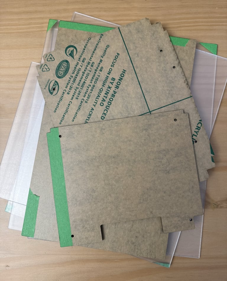
After getting it cut, I was able to insert the baseplate and route the bed wires through the new 12mm hole I added. I used the inner and outer groumets from the repo. My bed wires were pretty sure, but since I likely needed to move the bed inwards, it could be fine.
With the baseplate mounted, I could finally proceed with attaching the Z-Drives.
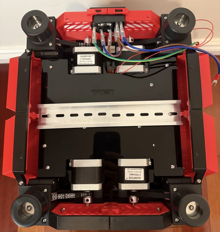
Z-Drives
I added blue Loctite all the grub screws in the Z-Drives. I already cut my four 700mm belts, so I routed them through the Z-Drives before mounting them.
I attached the Z-Drives based on the F-Zero CAD, but the V2.4 manual on page 41 also shows the attachment of the Z-Drives. The V2.4 gantry mounting (page 110) is mounted differently compared to the F-Zero.
I had to swap one NDN to an M3 nut per corner as the attachment point was close to the end of the extrusion. While mounting the NEMA17 motors, I pulled the motor to tension the closed loop belts.
I attached the gearbox bottoms and guitar feet along with the guitar feet risers. I had to use an M3 washer since the M3 head of the screw was too small to attach the feet.
With the Z-Drives mounted, I began attaching the belts to the attachment points. I ended up cracking one while assembling, so I printed some spares. I didn't have much belt leftover after attaching the belts to the rails so I didn't need to trim them. I didn't focus on tension that much as I would do that once my GT2 tension meter parts arrive.
I ended up using the 42mm electronics spacers since my deck panel would collide with the motors otherwise. I had to rotate the motors 90 degrees so the connectors were facing outwards.
After doing a test fit with the deck panel, it seemed to collide with the Z-Drives and motors anyway. I would need to redesign the panel. The side skirts seemed to fit well while the front skirt was too small and collided with the motor mount. I also needed to design a rear skirt that handles the power input and possibly add a fan.
Something I noticed that was different was that the CAD used an LRS-100 PSU and NEMA14 motors. That would explain why the clearance in the electronics bay seemed a bit cramped. Another thing I realized is I never cut any holes in the top panels for filament intake. I could either route it through the rear bottom or cut a hole for it.
Parts used:
- 4 x M3 Nuts (replaced NDNs)
- 8 x M3x35 BHCS (attach Z-Drives to frame, two per corner)
- 8 x M3x10 BHCS (attach Z motors to frame, two per motor)
- 12 x M3x8 BHCS (attach Z gearbox bottoms to Z-Drives)
- 4 x M3x16 BHCS (attach guitar feet)
- 4 x 3x7x0.5 Washer (attach guitar feet)
- 4 x M3x20 BHCS (for Z-idler tensioning)
- 8 x Heatset inserts (electronics spacers)
- 4 x M3x6 BHCS (to attach electronics spacers to baseplate)
Day 27 (Jan 10, 2026)
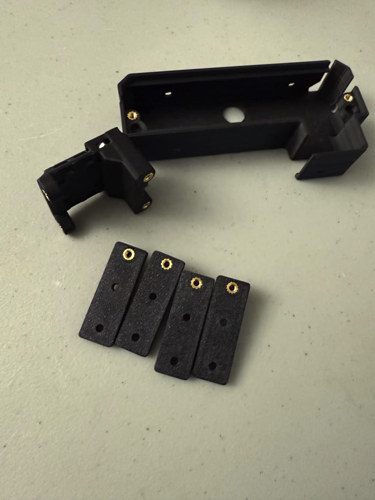
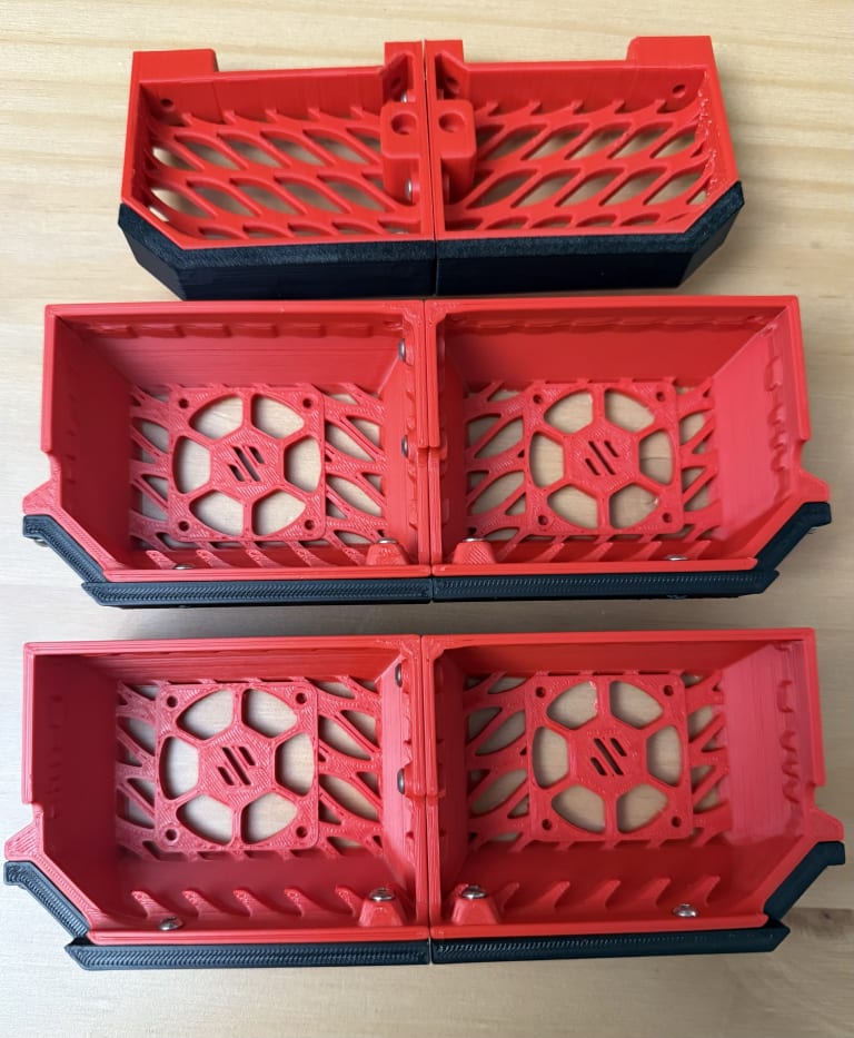
Skirts
I adjusted the front skirts in the CAD to provide more clearance for the motor mounts and added the Mini12864 display mount. Since I was using the same display as the Switchwire, I used the Switchwire CAD and replicated the dimensions for the skirt mounting.
For the rear panels, I duplicated the front skirts without the display mount. I added the power inlet into one of the skirts.
I wanted to add at least one 4010 fan to the side skirts to cool the controller board and the Raspberry Pi. The DoomCube Discord already had a few designs, so I decided to use Skippy34's 3mf file which had all the parts needed for an F-Zero. I uploaded a copy to GitHub so I could find it easier if I need it in the future. The skirts have one fan per part, so I could add up to four 4010 fans.
Files:
- Front skirt CAD
- front_skirt_A_x1.step
- front_skirt_B_x1.step
- Rear skirt CAD
- rear_skirt_A_x1.step
- rear_skirt_B_x1.step
Panels
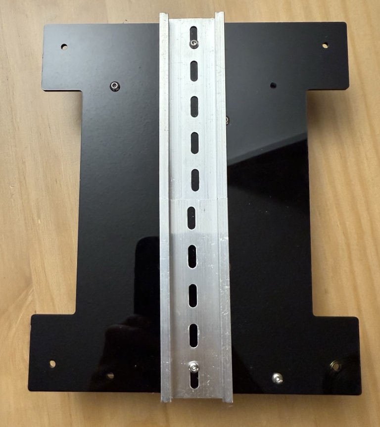
I updated the deck panel to add holes for the LRS-150-24 PSU. I got the dimensions and holes from the MEAN WELL datasheet. I also added holes along the centre X-axis for potential DIN mounting.
I intended to mount my electronics on the baseplate rather than the deck panel. Since I already cut the baseplate and didn't want to uninstall it, I created a DIN mount using two existing panel holes. The DIN mount would have five heatset inserts to mount a DIN rail and two to mount the part to the baseplate.
Files:
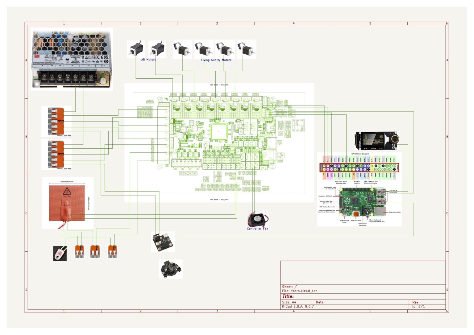
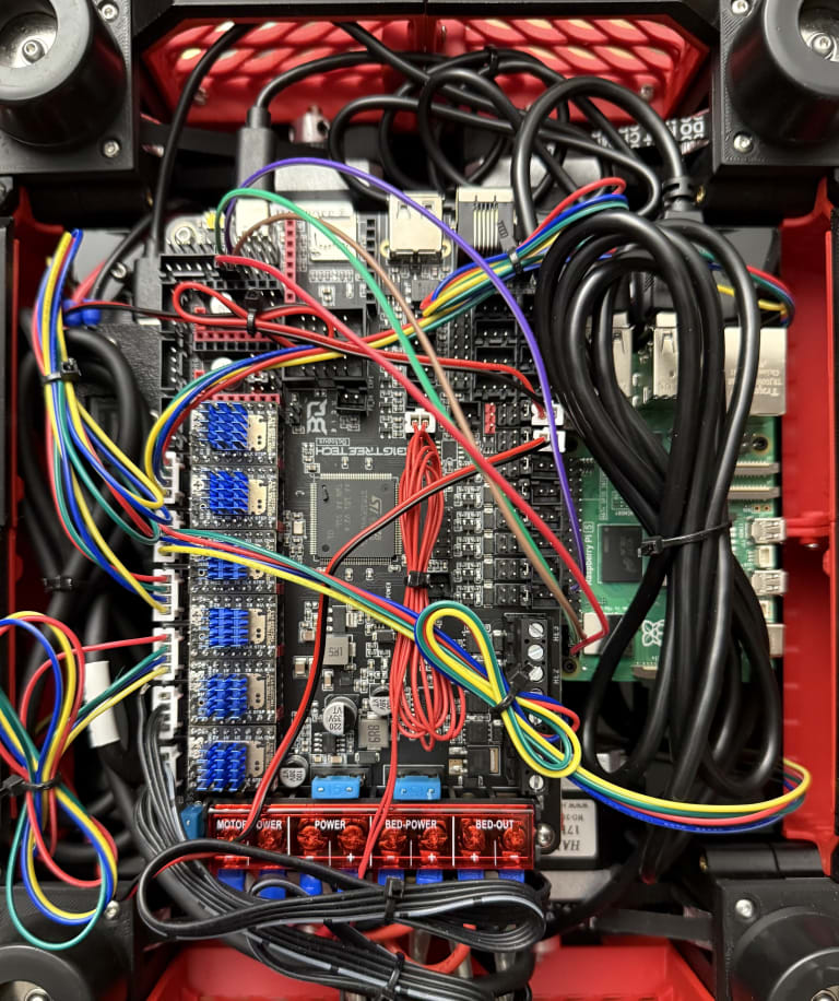
Wiring Diagram
Since there weren't any wiring diagrams for the F-Zero, I decided to sketch it out before assembling. I used KiCad to design my schematic.
I imported images of the parts and connected wires as I added more parts. I referenced the Voron manual website and PDF manuals for the V0 and V2.4 to ensure I didn't miss any components.
Since I was using the Nitehawk toolhead, a lot of the wires were removed from the BTT Octopus controller. I decided to connect the Octopus to the Raspberry Pi using USB rather than UART. I might swap it over later depending on how setup goes. I also wired two 5V and ground wires to the Pi for redundancy and to spread the load across the wires.
Files:
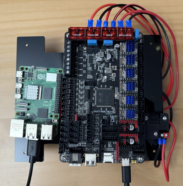
Fitting the Electronics
I started looking at the dimensions of the BTT Octopus (160mm x 100mm), Raspberry Pi 3 (85mm x 56mm), and LRS-150-24 PSU (159mm x 97mm). The Octopus and Pi would not be able to fit together on the baseplate as the Octopus is much larger than I thought. If I wanted to mount the Octopus and Pi together, I'd need to rotate the Octopus so that it's parallel vertically with the Pi and mount it on the deck panel rather than the baseplate. The PSU would then be mounted on the baseplate.
This might actually be better as the 120V of the PSU would be hidden by the deck panel and the parts I'd most likely tinker with, the controller board, would be easily accessible from the bottom. I could also use M3 standoffs off the electronics spacers to provide more clearance for the existing deck panel so that I wouldn't need to cut another.
For this solution, I would need to design a mount for the PSU and the electronics on the deck panel.
An alternative is recutting the deck panel with my updated mounts and mounting both a DIN rail and the PSU to the panel. This could be better as the PSU would be off the baseplate which could saturate in heat due to being close to the bed. I would likely need to add spacers for the PSU mounting as the heads of the screws or M3 nuts for the DIN rails would collide with the bottom of the PSU.
Day 28 (Jan 11, 2026)
Electronics
I created a PSU mount bracket for the existing baseplate panel. It would use one existing hole with an M3 nut and an M3 bolt to secure one point. Two heatset inserts would be added, one to attach the mount to the panel and one to attach the PSU to the mount. This would result in two mounting points.
I also updated the deck panel so that the PSU could be mounted in four orientations. If the PSU is mounted, the holes are covered anyway. I ordered DIN rails from Amazon as it ended up being cheaper per piece than AliExpress. I choose 4 inch (~10 cm) rails as I could fit two of them in the bottom of the F-Zero. It's more flexible than getting longer rails.
Files:
- PSU mount Fusion file
- psu_mount_on_baseplate%20v1.step
- Deck Panel v6 Fusion File
- Deck Panel v6 dxf File
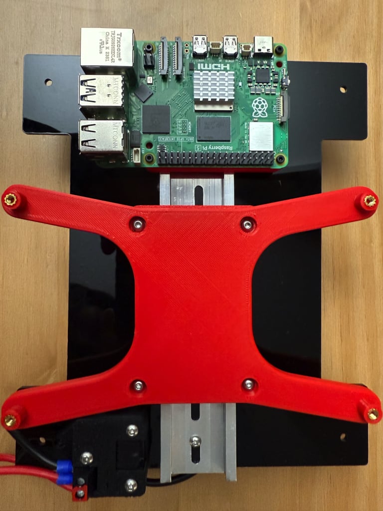
I plan on using MyStoopidStuff's remixed Raspberry Pi mount. I preferred this over the original as it has a tighter DIN mount. I picked the model the screwhead pockets and the 3mm standoff mount.
Enigma's vertical BTT Octopus DIN mount. I picked the remixed version rather than the original as I preferred having heatset inserts rather than self tapping screws.
Day 29 (Jan 13, 2026)
Electronics
I got the new deck panel cut at the YorkU Markham Makerspace, and did a fit of the DIN rail and power supply. I first mounted the DIN rail using two M3x6 BHCS and M3 nuts. I then mounted the LRS-150-24 using two M3x8 BHCS for the threaded holes. I used M3x10 BHCS for the two non-threaded mounting holes along with M3 nuts. I used an M3 nut between the panel and the PSU as a spacer due to the DIN rails taking more space. After mounting, the PSU was very secure. I somehow managed to place my DIN rail holes in all the locations that didn't have a matching mounting hole.
The clearance for the electronics on the underside of the deck panel was pretty tight. I test fit the 35mm spacers, and it seemed to fit better. Thus, I replaced the 42mm spacers with the 35mm ones. This would give a bit more room for wiring later on.
I also extracted my old power inlet from the V0.2 since the AliExpress one I got had thinner wires and I wasn't confident in using it. I used guitar picks and pry tools to get it out.

Parts used:
- 2 x M3x6 BHCS (DIN rails)
- 2 x M3x8 BHCS (PSU)
- 2 x M3x10 BHCS (PSU)
- 8 x M3 nuts
- 8 x Heatset inserts (35mm spacers)
Skirts
I ended up reducing the gap on the wrong side of the skirts, so I had to remodel the front and rear skirts. I forgot to make the inner hole of one of the rear skirts smaller so the two could connect together.
One issue was that since the inlet was not centred, it would collide with the motors. Thus, I needed to modify it again to centre the inlet. Even centred, it seemed that the inlet might collide with the motor mount or the cables from the cable chain. The skirts also collided with the screws of the motor mount.
I tried designing an inlet on the side skirts, but I didn't like how the power cable would protude a significant amount from the side.
I ended up needing to do multiple iterations on the rear skirts until I landed upon the version below. I also added 2mm more clearance for the motor mounts.
Files:
- Front skirt CAD
- front_skirt_A_x1.step
- front_skirt_B_x1.step
- Rear skirt CAD
- rear_skirt_A_x1.step
- rear_skirt_B_x1.step
- rear_lower_trim_A_x1.step
- rear_lower_trim_B_x1.step
I was able to get an M3 heatset insert on the side of the rear skirt to attach the two skirts together before attaching it to the printer. I used an M3x8 BHCS to attach the two skirts together before using two M3x12 BHCS to attach the skirts to the frame. It turns out that I didn't completely extend the holes for the skirts to go all the way through, so they were only mounted using the centre holes. Since the rear skirts were snug, I decided not to reprint them, but I did update the CAD.
Parts used:
- 1 x Heatset insert
- 2 x M3x12 BHCS
- 1 x M3x8 BHCS
Flying Gantry
I mounted the Flying Gantry onto the printer as it needs to be on to measure the belt tension with the tool I have in the mail.
I reattached the gantry wire organizer using the hardware I removed before. I ended up swapping the two M3x8 BHCS that screw up into the motor mount with two M3x6 BHCS. I also added a heatset insert to the part that would connect to the cable chain.

The end of my cable chain had holes that didn't align with the angled bracket, so I needed to redesign it to fit the holes. I ended up using 18 of the cable chain links plus one of the ends. I did this to give more of a bending radius.
Parts used:
- 2 x M3x6 BHCS (wire organizer)
- 1 x Heatset insert (wire organizer)
Removed:
- 2 x M3x8 BHCS (previously for attaching wire organizer)
Files:
Electronics Continued
I started planning the actual runs of my wires. My AB motor wires need to be extended as they aren't long enough to go through the cable chain. I decided to print Richie494's Nithawk USB mount as it was smaller than the standard one. I also printed m0ep's M3 DIN brackets so I could use heatset inserts for my Octopus mount.
The Octopus mount itself seemed to have undersized holes for the M3 heatset inserts. I was still able to get inserts in, but it wasn't ideal.
Since it seemed there was no standard for the distance between the holes for DIN clips, I decided to just make my own. I used parameters in Fusion to make future adjustments easier. I used the Voron 2 DIN Clips CAD and was able to easily modify it on Fusion.

Parts used: Nitehawk
- 5 x Heatset Inserts
- 3 x for Nitehawk mount
- 2 x for DIN clip
- 3 x M3x12 BHCS (to mount Nitehawk)
- 2 x M3x8 BHCS (to mount to DIN clip)
BTT Octopus
- 8 x Heatset Inserts
- 4 x for BTT Mount
- 4 x for BTT DIN clips
- 4 x M3x8 BHCS (to mount to DIN clips)
Files:
- DIN Mount Fusion File
- For BTT mount - Stiffer_DinMount_M3_insert%20v1%2048mm%20centre.step
- For Nitehawk USB mount - Stiffer_DinMount_M3_insert%20v2%2050mm%20centre.step
Day 30 (Jan 15, 2026)
Skirts
With the rest of the skirts printed, I was able to attach the remaining. I used different sized screws based on which would fit best. I intially used M3x8 BHCS on all the trim pieces, but it ended up blowing out the other side of the trim piece, so I swapped to M3x6 BHCS. I also attached the deck panel with M3x6 BHCS to see how everything fit. Overall it looked alright, but the DIN rails collided with the side skirts which resulted in them bending a bit.
Parts used: Assembly & Mounting
- 10 x Heatset inserts (8 for sides, 2 for front)
- 8 x M3x8 BHCS (to mount side skirts to frame)
- 2 x M3x16 BHCS (to mount front skirt) Trim
- 4 x M3x8 BHCS
- 4 x M3x12 BHCS
- 8 x M3x6 BHCS Deck panel
- 4 x M3x6 BHCS
ZeroPanels
With all my panels cut and panel mounting clips printed, I started the assembly for the ZeroPanels.
First, attached the foam tape to the panels. I peeled only the edges of the acrylic panel backing to keep the rest of the panel clean. I used 3/8" wide and 3/16" thick foam tape from Amazon. It was wider than the recommended BOM, but it was what I had on hand from my V0.1 ZeroPanels.
After attaching the foam tape on all the panel edges, I put my box of printer parts on the panels to let the tape sit. (the MicroSD card was taped onto the panel to remind me which SD card was for the V0.2)

I then worked on attaching the double-sided tape to the clips. I had plenty of 2 mm wide VHB tape leftover from my other Voron builds. I measured the length of tape needed for each clip and cut the strips. I then cut the strips lengthwise into thirds before attaching them to the clips.

With the clips and panels complete, I did a test fit without removing the VHB tape's backing. The unbranded VHB from my Formbot kit didn't seem very high quality and the stickiness was mediocre.
Since everything fit well, I attached the panels to the clips and mounted the panels. I would probably need to trim some of the foam near the Z-linear rails as the carraiges protrude slightly from the frame and would rub against the foam.
I noticed that one of my side panels wouldn't fully click in on the bottom. After further examination, it seemed that the bottom of the panel clip was colliding with the skirt. I imported the STL into Fusion and modified the corners to have a flat bottom. I had to import the STL file into Fusion via the Insert Mesh command as the object would otherwise be 10 times larger.
Unfortunately it seemed that after using a new spool of Jet Black Polymaker ASA, I started having issues with clogging and under extrusion. This might also be due to heat creep, but I never had issues with this on my other two ASA spools. I decided to stop and print the remaining bottom hinge another day.
To ensure the adhesion of the panels I did have assembled, I placed books and other heavy boxes on the assembled panels.
Files:
- Localizing clip corner Fusion file
- localizing_clip_corner_flat_slide%20v1_A_x1.step
- localizing_clip_corner_flat_slide%20v1_B_x2.step
- zp_hinge_bottom_fixed_v3_x1.step
Day 31 (Jan 19, 2026)
ZeroPanels
I swapped back to my previous roll of ASA filament and was able to print the final bottom hinge and trim for the rear skirts. It seemed that my new roll of filament might have been wet, since I didn't have any problems once I swapped back to the other roll. I used 3M branded VHB tape for the new panel and it stuck much better than the Formbot tape. One of my clips ended up breaking when removing the panels from the printer, so I'd need to reprint it. This was one of the two clips that were printed using the wet ASA filament. I would probably need to reprint both since the clogging left the parts very brittle.
I was able to friction fit four magnets into the hinge components. I did need to hollow out one of the holes, but else it worked pretty well. I might add superglue if the magnets start falling out. The door sat slightly slanted, but it seemed to seal well enough. I needed to print the handle.
Parts used:
- 4 x 6x3mm magnets
Skirts
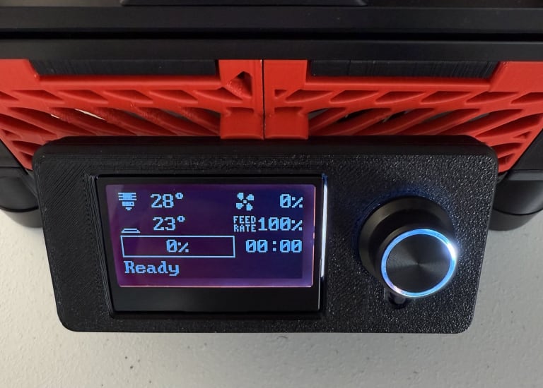
With the final trim piece printed, I added two heatset inserts and installed it onto the rear skirts. For the display, I had a Mini-12864 Display like the one from my Switchwire. I accidentally ordered a version with a front inserted SD card slot, which was wider and took more depth than the side mounted option. I had the Fysetc display that didn't work for my Switchwire, but I never tested the direct cable connection to the controller board. I decided to try my Fysetc display first before redesigning the display housing for the other display. This way I could use the existing Switchwire display case if it worked.
I did have to redesign the front skirts to allow for the cable to pass through. I added a cutout to one of the skirts to prevent the need for reprinting both. I also filled in the centre frame mounting hole due to being unable to screw in from there.
Parts used:
- 2 x M3 Heatset inserts (for rear trim)
- 2 x M3x6 BHCS (for rear trim)
Files:
- lcd_case_front_mini12864.stl
- lcd_case_rear_mini12864.stl
- Front Skirt Fusion file
- front_side_skirt_A_x1.step
- front_side_skirt_B_x1.step
Electronics
DIN Mounts
I got a Raspberry Pi 5 8GB from uOttaHack, so I installed that using M2x10 self-tapping screws. It was way overkill, but my other two Pi's had issues (one USB boot only, other was the Pi that failed on my Switchwire). It is easy enough to swap in the future though due to the mount.
I had precrimped 16 AWG wires which I used to attach to the power supply. I stripped the other end and inserted it into my two Wago 221-415 connectors which I attached to the deck plate using VHB tape.
I attached all the DIN mounts to the DIN rails, and it didn't seem like the Nitehawk would fit alongside the BTT Octopus. I removed the Nitehawk from the DIN mount and use the original adapter mount and used VHB tape to attach it to the deck panel.
Parts used:
- 4 x M2x10mm self-tapping screws
Removed:
- 2 x M3x8 BHCS (to mount to DIN clip)

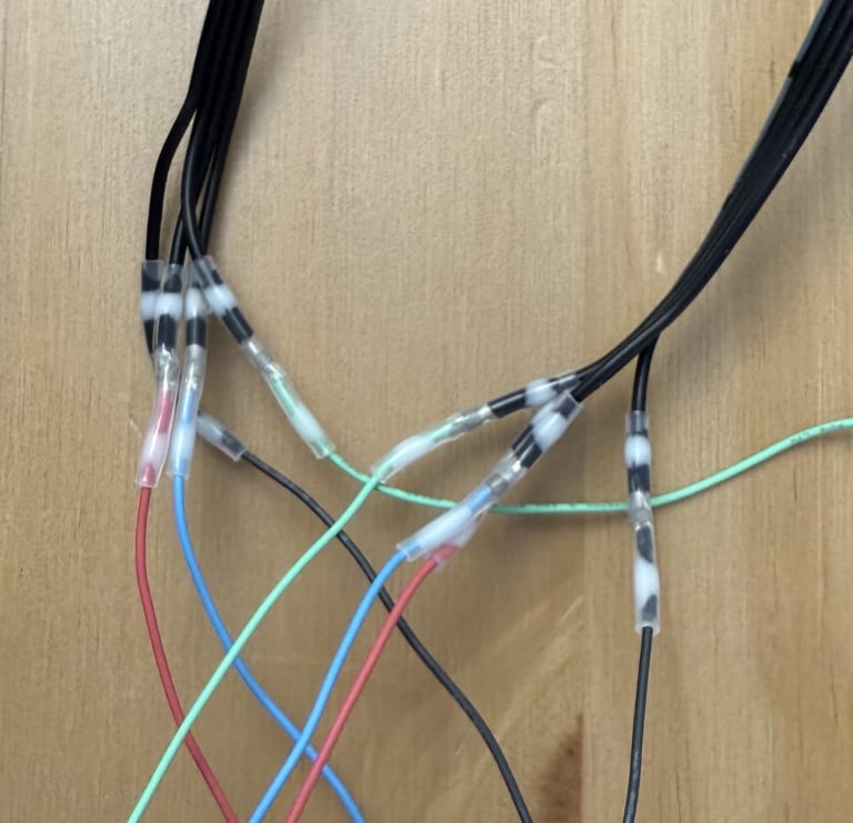
Motor Cables
I started crimping my motor cables. I used my IWISS IWS-2820M crimper on the 1.3mm width setting. First, I cut two of the cables I'd use as an extension for my AB motors. These came with one of my V0 kits (22 AWG).
After crimping the end of those, I crimped the wires that came with my Z-Drive motors. These were pre-stripped, so I just trimmed the ends a bit to properly fit the crimp. For wiring order, I did:
- Blue (A-)
- Yellow (A+)
- Green (B+)
- Red (B-)
The BTT Octopus motor pin outs were:
- A1
- A2
- B2
- B1
I decided to crimp all my cables now as I wanted them ready for when my controller board arrived. The stiffer cables included with the motor were much easier to crimp than the flexible extensions that came with my V0 kits.


Controller Fans
I attached two 4010 24V fans to the side skirts which were on the BTT Octopus side. I had them push air into the electronics bay rather than pull to ensure the motor drivers have sufficient cooling. I ended up orienting the fan cables the furthest from the controller by accident, but didn't want to remove the screws to rotate them.
Parts used:
- 8 x M3x16 BHCS
- 8 x M3 Nuts

Toolhead
I used two M3x8 BHCS to attach the PUG gland and Nitehawk cable to the strain relief mount. I used a zip tie at the top of the PUG gland.
Parts used:
- 2 x M3x8 BHCS
Day 32 (Jan 20, 2026)
Electronics
Motor Cables
The Voron 2.4 manual recommends 18 AWG wire for the controller board. I had some 16 AWG wire, but wouldn't have enough for all the cables. I ordered some more 16 AWG silicone stranded wire from Amazon
For my AB motor cables, I used solder heat shrink to connect the two cables. The AB motor cables seemed to be 24 AWG, but the two cables connected well with solder. I use my heatgun on the 750W setting to slowly melt the solder.
Bed
I replaced the Wago 221-412 connectors for my bed Wago 221-2401 in-line connectors. It didn't make sense for the cables to come out on the same side and this allowed the wires to take less space.
I also picked up a POWERFIST 25 connector kit from Princess Auto for $10, but it didn't have any in-line connectors.

GT2 Belt Tension Meter
My GT2 meter kit didn't come with grease, so I bought some PERMATEX High-Performance Synthetic Grease for $12.
I followed the assembly instructions for the tension meter.

Gantry and Toolhead
I had to remove the flying gantry from the Z-Axis to access the front idler adjustments. I noticed that my M3x12 BHCS were not long enough to catch the idlers, so I replaced them with two M3x16 BHCS with an M3 nut to act as a spacer.
I adjusted my belts until they were around 2.0 on the tension meter. After the belts were adjusted, I mounted the toolhead.
The toolhead wasn't able to fully seat on the bottom. I trimmed part of the part cooling fan corners as I thought that was the issue, but after that I still wasn't able to properly mount the toolhead. It seemed that the excess belt was preventing the toolhead from being mounted, so I trimmed the belts until there were only 3-4 teeth of excess coming out from the x-carriage. With the trimmed, belts, the toolhead fit vertically properly. I also added an M3x20 BHCS to further secure the toolhead to the x-carriage from behind.
Parts used:
- 1 x M3x20 BHCS (to secure x-carriage to toolhead from the rear)
- 2 x M3x16 BHCS (idlers)
- 2 x M3 Nuts (idlers)
Removed:
- 2 x M3x16 BHCS
After mounting the toolhead I noticed a few issues:
- The Eddy mount screws (to attach the Eddy probe to the brace) hits the extrusion before the x-gantry
- The PG7 cable gland I had is too small for both the Nitehawk and the Eddy probe cable
I would need to redesign the Eddy mount (and possibly find screws that protrude less) and redesign the electronics area on the gantry. I might use PUG as it enables me to route cables without needing to depin the Nitehawk.
Day 33 (Jan 21, 2026)
Gantry and Toolhead
I redesigned the gantry electronics bay area to add one more hole and a possible hole for a PTFE tube. I decided against using the PUG and going back to the PG7 since creating the PUG mount I created would make printing the part difficult.
For the Eddy mount, I replaced the M3x18 SHCS with M3x20 BHCS as the socket heads took a lot more space. The mount fit fine, but I am a bit concerned with how close the mount is to the heater block. I'll shift the mount forward a bit again later.
Parts used:
- 2 x Heatset inserts
- 2 x M3x20 BHCS
Removed:
- 2 x M3x18 SHCS
Files:
- Gantry Electronics Bay Fusion file
- gantry_electronics_bay.step
- Eddy mount Fusion file
- mount v12.step

Day 34 (Jan 22, 2026)
Toolhead
I replaced the M3x20 BHCS used to reinforce the x-carraige and toolhead with an M3x25 BHCS as the M3x20 wasn't properly catching the M3 nut in the toolhead.
Parts used:
- 1 x M3x25 BHCS
Removed:
- 1 x M3x20 BHCS
Files:

Day 35 (Jan 29, 2026)
Flashing Electronics
Since my BTT Octopus arrived, I decided to flash the controller board before installing it.
Before flashing the board, I followed the Voron V2.4 manual and the docs page for how to prepare my jumpers. Since my fans were all 24V, I set all my fan jumpers to 24V.


Flashing Mainsail
I flashed Mainsail as usual with both the Wifi and SSH credentials set.

Flashing BTT Octopus
With Mainsail flashed, I inserted the MicroSD card into the Pi and SSH'd into it once it booted.
I build the firmware image with the following commands:
sudo apt install make
cd ~/klipper
make clean
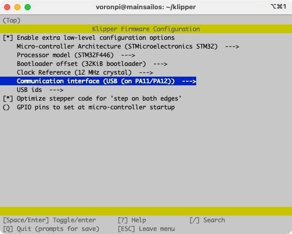
make menuconfigMy processor was the F446, so I used the settings as prescribed in both the Voron documentation and BTT documentation.
I wanted to try using UART over USB (to reduce cable clutter) so I selected Serial (on USART2 PD6/PD5) for the communication interface.

scp voronpi@10.0.10.111:/home/voronpi/klipper/out/klipper.bin ~/Downloads/
I formatted the MicroSD card to FAT32 and using MBR. I copied the klipper.bin file and renamed it to firmware.bin.

I inserted the power selection header jumper (D51) near the center of the board to enable USB C power.
After insertting the SD card and powering on the Octopus via USB C, I waited 10 or so seconds before unplugging the power and pulling the MicroSD card. I checked the SD card and the file was now renamed FIRMWARE.CUR, which meant that the flash should have worked. I connected the PD6 (RX2) pin on the Octopus to Pin 8 (TXD) on the Pi and PD5 (TX2) to Pin 10 (RXD).
I used the default V2.4 configuration and some of the changes below:
sensor_type: Generic 3950for bed and extruderheater_pin: PA1as I'm usingBED_OUT- Commented out
Probesection as I'm planning on using Eddy probe position_max: 120which will likely need to be adjusted, but based on V0- Updated
[quad_gantry_level]to addgantry_cornersandpoints, would need to adjust - Modified sensorless homing based on Voron documentation and my previous V0.2 config
- Set
heater_pin: PA0for extruder, but will need to modify entire section for Nitehawk
After getting rid of all the errors, I wasn't able to connect the MCU over UART. MainsailOS had UART enabled by default, but it was hard to debug when I didn't know if it worked at all.
I decided to flash the Octopus again with the same config as earlier, except I used USB (on PA11/PA12) for the communication interface. After flashing and confirming the file was renamed FIRMWARE.CUR, I realized I couldn't connect the Pi to the Octopus as the USB C port was being used to power the controller board. I decided to pause for now until I got the board installed into the machine. I installed six of my TMC2209 drivers since that was all I needed. I could use the other two for another project.
To crimp my 16 AWG wires, I used #8 Spade terminals and crimped with the A30J crimping die. I used the blue setting (middle) first, but notied that the wires were still loose. I then used the red setting (smallest) to ensure that the crimp was tight. I wired the controller board so that all the power wires went towards the power supply since I didn't want any interference with my USB connections.
I had removed the DIN rail since I had a 150mm DIN rail coming, which should be short enough to not collide with the skirts.
Added:
- 4 x M3x6 BHCS (BTT Octopus mount) Removed:
- 2 x M3x6 BHCS
- 2 x M3 Nuts
Printing Remaining Parts
My PolyDryer arrived, so I dried my black roll of PolyMaker ASA for 6 hours at power mode 2. It was initially at a 44% humidity according to the hydrometer.
Day 36 (Jan 30, 2026)
Printing Remaining Parts
I left the ASA to dry overnight and it reached 27% humidity. I did a test print using an air exchanger for the PolyDryer, and the print finally completed. There was a few layers that had issues with extrusion, but it was much better than before. The humidity dropped to 18% by the end of the print, so I printed the remaining parts.
I did encounter some more extrusion issues, so I disassembled and reassembled the Stealthburner to see if that would fix it. I had some issues with a few layers, but was able to get parts printed with minor underextrusion. The filament's humidity stuck at 10% throughout the print.
Toolhead Electronics
My depinning tool arrived, so I was able to depin the Nitehawk's Micro-Fit 3.0 connector and feel the cables through the gland.
I had to shave down the inside of the PG7 gland to fit the Eddy probe through before adding it to the toolhead. Testing the movement of the toolhead, I noticed that the Eddy's cable does get squished under the XY joints, so I might need to shave or redesign it to add more clearance under the linear rail.
To route the cables, I reattached the flying gantry to the frame. I then connected the two AB motor cables and fed the cables through the cable chain to the bottom of the printer. I ended up snapping a portion of the electronics bay mount, but it didn't affect routing. With the toolhead cables routed to the bottom of the printer, I started cleaning up the electronics bay.
Electronics
I started connecting all the cables to the controller board and Pi. I used zipties to tidy up most cables. For the Nitehawk and Eddy cables, I wrapped the extras in an eight pattern to reduce possible interference.
I still had to modify the feet risers as the TMC2209 drivers and cables stick out from the bottom quite a bit. I may also design a bottom panel to enclose the bottom.
Day 37 (Feb 3, 2026)
Electronics
Controller Board
I unplugged the Eddy probe and Nitehawk to ensure I got the right MCU path for the Octopus. I plugged the printer in and turned it on. I SSH'd into the Pi and ran ls -l /dev/serial/by-id/* to get the device ID (usb-Klipper_stm32f446xx_4E002D000451343437373238-if00). I added that to my printer.cfg, then shutdown the Pi to plug in the Nitehawk and determine the device ID of that.
The controller fans were annoying since they were always at 100% power, so I moved them from the J56 and J57 slots to J54 and J55 which are controlled by pins PD14 and PD15 respectively.
I also had a warning that my Pi was undervolted.
Nitehawk
The Nitehawk should be preinstalled with Katapult and Klipper. After plugging in the Nitehawk USB adatper to the Pi, I turned on the printer.
I ran ls -l /dev/serial/by-id/* again, and got the device ID of the Nitehawk (usb-Klipper_rp2040_32323232361986A7-if00).
I followed Modbot's advice and copied the relevant parts from the Nitehawk config to my printer.cfg. After adjusting the config, I got an error that the extruder temperature was out of range.
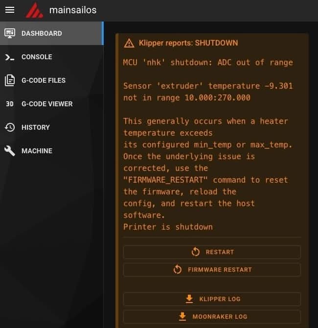
This could be due to my crimping or the wires getting squished while assembling the Dragon Burner. I turned off the printer and disassembled the toolhead to inspect the thermistor wire.
After examining the thermistor, there was indeed a loose connection as one of the wires fell out of the connector. I decided to replace the thermistor as the cable was already short and some insulation was damaged due to the multiple reassemblies. I had a Siboor NTC100K thermistor which I crimped and installed.
After booting up the printer again, I got a missing config message "Make sure you include the mainsail.cfg in your printer.cfg file." After adding [include mainsail.cfg] to the top of the printer.cfg, I had no errors.
I decided to focus on adding more clearance to the bottom so I could flip over the printer.
Bottom Spacers
I redesigned the spacers and Z-Drive gearbox bottoms to provide additional clearance below the printer. The original spacer was around 5 mm thick, while I added an additonal 30 mm of clearance.
I also added a mount on the rear trims to provide further reinforcement on the rear skirts. These would screw into the gearbox bottoms and provide more rigidity when plugging and unplugging the power cord:
Files:
- Rear skirt CAD
- rear_lower_trim_x1.step
- rear_lower_trim_mirrored_x1.step
- Foot Riser CAD
- guitar_foot_riser_x4%20v4.step
- Z-Drive CAD
- z_gearbox_bottom_x2.step
- Mirror in slicer to get other two corners
I had some warping on two of the gearbox mounts, so I installed the two good ones in the rear while I printed the rest. I used M3x40 BHCS for the feet which were quite long, but since I planned on adding a bottom panel and there was plenty of extra room under the heatset insert on the gearbox bottom.

Files:
Parts used:
- 2 x M3x10 BHCS
- 4 x M3x40 BHCS
- 8 x Heatset insert
- 2 x for trim
- 2 x for display mount
- 4 x for gearbox bottom
Removed:
- 2 x M3x8 BHCS (previously for gearbox bottom)
- 4 x M3x16 BHCS (previously for guitar feet)
Day 38 (Feb 12, 2026)
Eddy Mount
The screws on my Eddy mount collided with the rear X extrusion whenever the toolhead was all the way back. I redesigned the mount to provide just enough clearance for the screws.
Files:
Parts used:
- 2 x Heatset inserts
Bed Mount
My bed was too far forward, so I printed an extended version (v2) of the bed mount beyond I needed to determine where exactly I needed the heatset insert. After doing some repositioning, I determined the final hole that was needed and designed a v3. I placed three holes right next to each other to provide further fine tune control over which hole to use. I still needed to adjust the height of the bed as the front sat lower than the rear.
Files:
- Front Bed Mount v2.f3d
- Front Bed Mount v2.step - To determine hole spacing
- Front Bed Mount v3.f3d
- Front Bed Mount v3.step
Parts used:
- 1 x Heatset inserts
Filament Path
I needed to route my PTFE tube through the rear panel since there wasn't enough clearance for the top and I didn't want to feed it through the bottom of the printer. I printed Alexander's pass through. I needed to add a 32mm hole near the to of my rear panel. I decided to rip off the double sided tape from the panel as it wasn't sticking well and I would replace it with 3M later on.
Parts used:
- 3 x Heatset inserts

Mini12864 Display
I started following the Voron guide for the display. I flipped over my connectors as I had a Fysetc display and a BTT board. I added my EXP cables and left the flashing for another day.
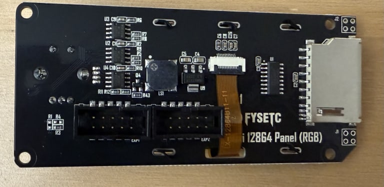
Skirts
My controller fans didn't feel very strong, so I decided to add two more to the opposite skirts in a pull configuration. I plugged these info the J52 and J53 ports which were controlled by PD12 and PD13 respectively.
Parts used:
- 8 x M3x16 BHCS
- 8 x M3 nuts

Day 39 (Feb 16, 2026)
Filament Path
I modified my rear panel to include a 32mm hole for the PTFE passthrough along with three holes for the screws. I used M3x10 BHCS to secure the passthrough to the rear panel. I added a extruder collet before fully screwing in the passthrough. I also decided to reattach my corner pieces using 3M tape.
Parts used:
- 3 x M3x10 BHCS
Files:

Day 39 (Feb 22, 2026)
Z-Belts
I used the belt tension meter to get my belts to around 2.6 on the meter.
Filament Path
I attached a 4x3 PTFE tube from the rear panel to the toolhead. It was too short, but I left it in place for now.
Day 40 (Feb 24, 2026)
Mini12864 Display
I was working with BTT support, and wanted to get the display back to where it lit up with no information. I pasted the following from the V2.4 Octopus Config and to my surprise, the screen lit up with all the printer details. The screen was slightly red, but I modified the gcode for the RGB until it was a solid white. It seems that the display didn't need flashing but I'm not sure really changed.
I ended up using M3x20 BHCS to attach the screen to the skirt as the threads weren't catching. The display was dim whenever the Neopixel gcode was run, so I commented it out for now. There is a red border around the display, but it is better than the dim display.
[board_pins]
aliases:
    # EXP1 header
    EXP1_1=PE8, EXP1_2=PE7,
    EXP1_3=PE9, EXP1_4=PE10,
    EXP1_5=PE12, EXP1_6=PE13,    # Slot in the socket on this side
    EXP1_7=PE14, EXP1_8=PE15,
    EXP1_9=<GND>, EXP1_10=<5V>,

    # EXP2 header
    EXP2_1=PA6, EXP2_2=PA5,
    EXP2_3=PB1, EXP2_4=PA4,
    EXP2_5=PB2, EXP2_6=PA7,      # Slot in the socket on this side
    EXP2_7=PC15, EXP2_8=<RST>,
    EXP2_9=<GND>, EXP2_10=<5V>
Parts used:
- 4 x M3x12 BHCS
- 2 x M3x20 BHCS