
Introduction
I bought a used Unifi US-8-150W on Facebook Marketplace to add to my network stack. It powered on fine and seemed to work, but the power port on the back was broken.

It would have functioned fine without replacing the port, but this seemed like a simple project and I'd have more peace of mind after it was repaired. The port itself was a standard IEC C14. I was able to order one from Aliexpress for a few dollars. The model was AC-07B rated for 10 Amps.
Repairing
Disassembly
I followed Orion_2012's forum post on how to disassemble the switch. On the back of the switch, I unscrewed the two screws.

I then placed my thumbs on top of the switch and applied slight downward pressure while pushing the top case forward.

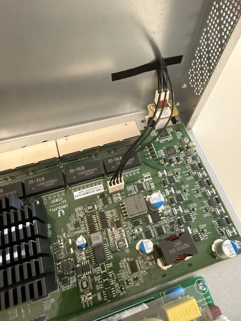
I slowly lifted the top case, and ensured that I didn't catch any cables. I rotated it so the face of the switch sat on the table. There is a cable that goes from the board to the front LED as shown below.
To remove the old power port, I tried pushing in the four tabs on the port's corners and shimmying it out.
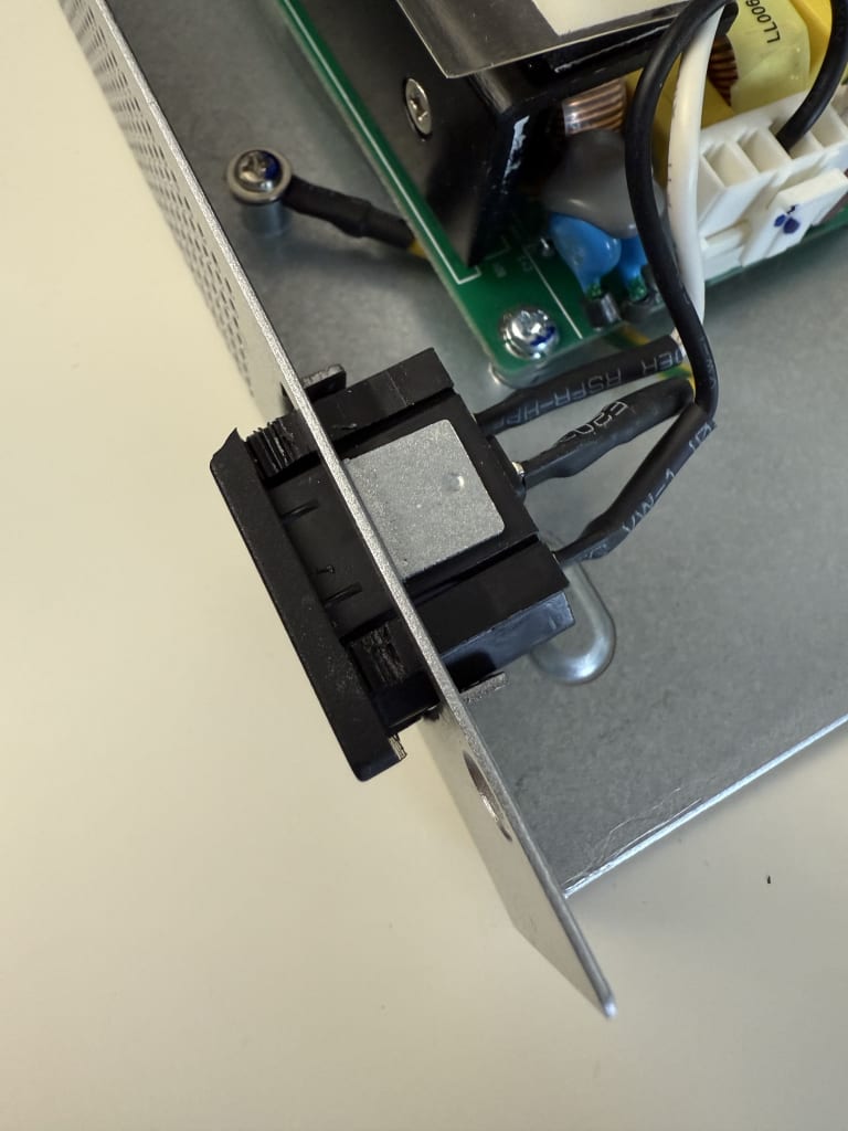
I was able to get the top tabs out, but the bottom tabs were difficult to get out due to the damaged port and the rest of the switch body. I decided to break off the top tabs since I wasn't reusing the port.

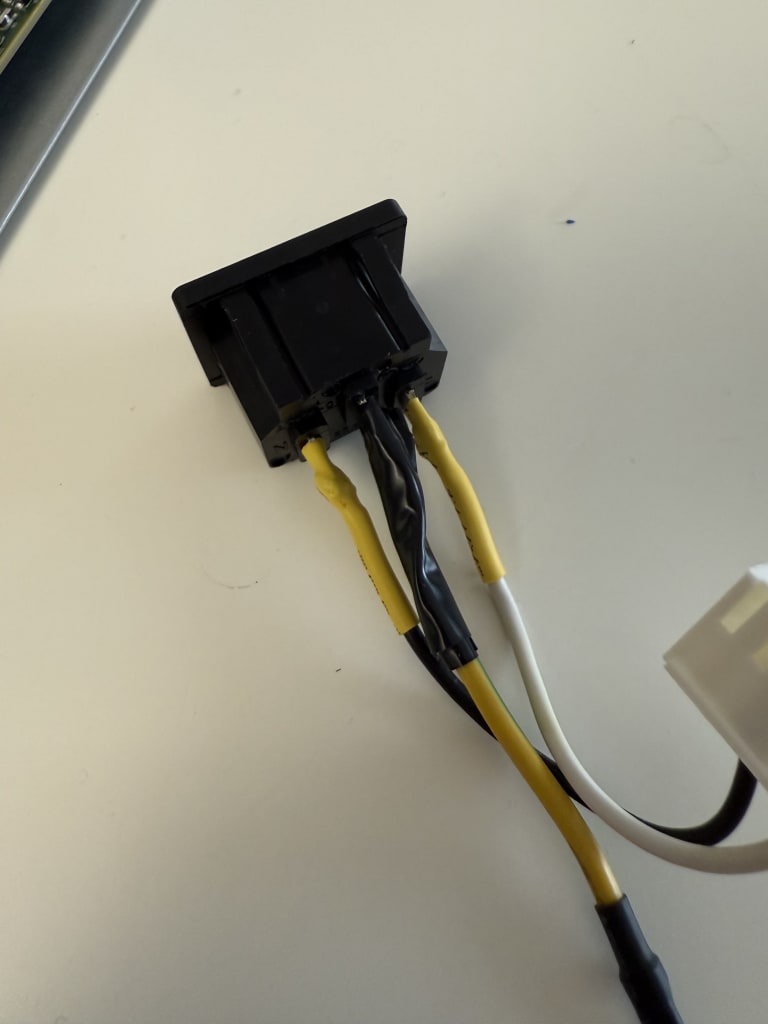
I was going to just unravel the wires from the old port, but noticed they were soldered on. I chopped any part of the wire covered by solder and proceeded to replacing the port. If I had to do it again, I would have cut the cables from the beginning.

Replacing Port
I restripped the wires (20 AWG) enough to double back on itself and added some heat shrink. The heat shrink for the ground cable ended up being to small, and I realized after soldering on the connector. My solder connections were not great at all, but they were mostly used to prevent the cable from moving. I added some electrical tape to the ground connector in place of heat shrink.
I did consider using crimped spade connectors, but since this was a permanent fix, I decided a permanent connection via soldering would be better.

Reassembly and Testing
I reinserted the port partially and plugged the wires back in. I lowered the top case so I could see the front LED, and plugged the switch in. The lights lit up, so I unplugged it and proceeded to push the port all the way in.


After double checking everything, I slide the top case back on and watched the bottom to ensure all the tabs went in place.

I plugged it in again, and the front LED lit up.

Conclusion
This project took a little under two hours, mostly as I needed to find my solder and heat shrink. It was pretty straightforward, and if I were to do it again I would cut the wires. Now the switch is ready to replace a dumb switch on my network.


