
Introduction
My home came with a DSC PC1550 panel and PC1500RK keypad. The system itself worked, but it wasn't able to connect to a system like EnvisaLink for remote access. I wanted to upgrade the panel and keypad so that the system could be remotely monitored. I was inspired by SnazzyLab's video where he installed a new system in his home. I bought a DSC PC1832 and PK5500 display to replace my system.
Swapping Keypad Housings
The keypad housing of the PK5500 I got was very yellowed. The PC1832 I ordered also came with a PK5501, the model with a segmented display. The housings were similar, so I swapped the two housings.
To remove the keypad from the housing, I inserted a flathead screwdriver into the two slots on the bottom of the keypad, below the keys.

To remove the PCB from the keypad, I used a plastic pry tool on the top while undoing the top clips. I did the same process with the PK5501 to remove it from the housing and keypad. One thing I noticed was that the PK5501 used a ribbon cable to attach the display to the PCB. The PK5500 used pads which pressed onto the PCB when the PCB was clipped back into place. I wiped everything down lightly with a paper towel as there were a lot of surface mounted components. I also wiped down the pads and connectors for the display and PCB before reassembling.


With that, the keypad had a newer housing that wasn't as yellowed.
Modifying the Panel Box
My PC1550 panel had plenty of wiring running into it. The box it was housed it seemed to come with the panel as it was labled PC1550. The mounts on the panel would not align with the newer PC1832, so I had to drill new holes into the box.
To remove the box while remembering the configuration of the wires, I removed pairs of wires one by one, rerouted then out of the box, then reconnected them to the PC1550. This way I could slowly remove the wires from the box while maintaining the order of the wires.
After the box was removed, I traced the holes from the PC1832 onto a piece of paper and drilled the holes into the box.

With the new holes, I reused the plastic standoffs and mounted the PC1832 in the box. If the standoffs broke, I was planning on buying some nylon ones from Sayal.

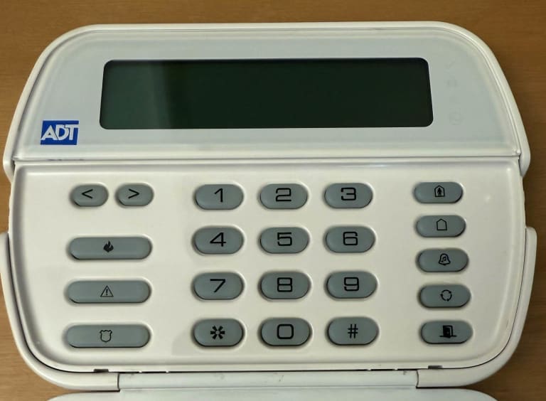
Replacing the PC1550RK Keypad
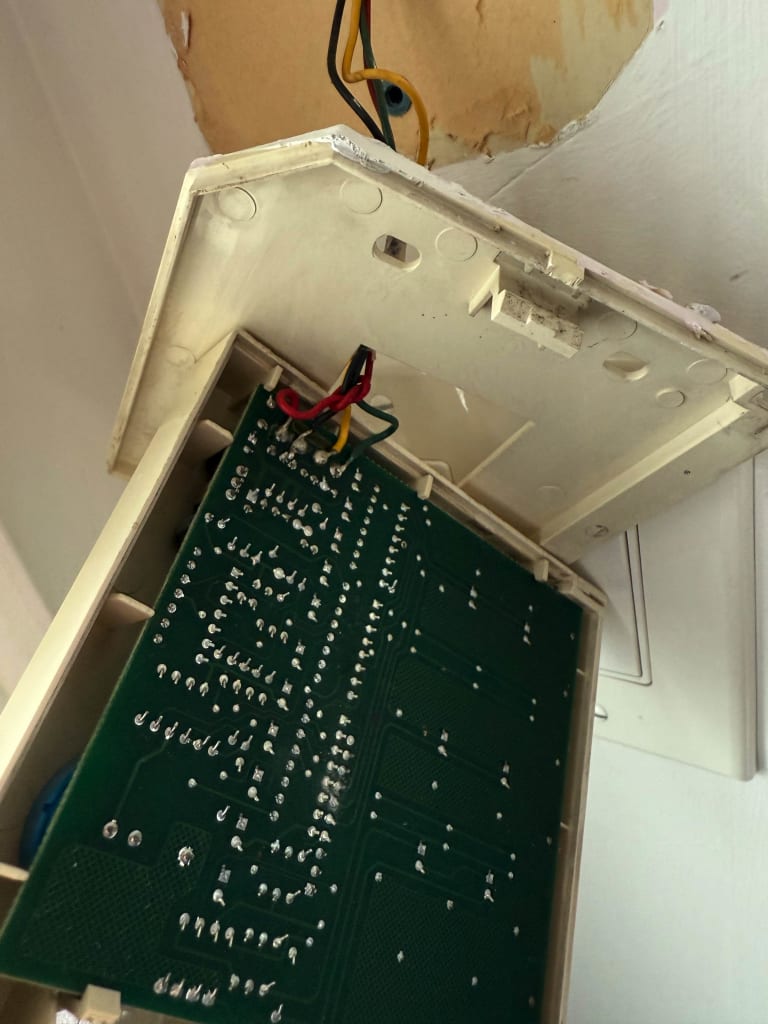
I decided to remove the keypad next. I used a screwdriver and pressed on the clip from the bottom of the housing. I noticed that the wires were soldered onto the PCB rather than screwed on. I trimmed the wires and restripped them (22 AWG) before mounting the new RK5500 keypad. Luckily the screw holes lined up to the previous mount and the wires were coloured correctly.
After inserting the wires into the new keypad, I mounted it onto the wall.

Replacing the PC1550 Panel
With the keypad and new panel in the box, all that was left to do was move the wiring from the old panel to the new one. Like before, I removed wires in pairs and moved them into the box. I attached them to the same label as on the old panel (Zone 1 to Zone 1, COM to COM, etc).
After double and triple checking the wiring, I connected the battery backup to the panel and also turned on the power to it.
The keypad lit up and the default installer code worked, but I decided to reset the system just in case.
Resetting the PC1832 Panel
I found the following two manuals very useful when programming:
I followed JasonTech's video for resetting the panel. I used a wired to jump the Zone 1 and PGM1 pins together. I turned on the system for 10 seconds or so, and then shut if off to remove the jumper.
After checking the keypad, I saw the version of the keypad and a blank date and time.
Programming the panel
I followed Alarm System Store's guide and video for how to program the keypad.
After setting the date and time, I changed the master and installer codes before proceeding with the rest of the programming. My system didn't properly register all the contacts as closed until I entered programming section 013 to disable option 6 and enable option 1 (not using resistors). After that, the system was ready to arm and the zones that I programmed were properly detected.
To rename the used zones, I followed the instructions from the PK55XX manual for Programming Labels:
- [*][8][Installer Code][*]
- [*] then the section/zone code to relabel
- Use keypad to rename the zone
- [*] then scroll to "Save" then press [*] The ASCII characters could be accessed by pressing [*] then scrolling to select the characters. The ASCII table and mapping of numbers to letters were also on the manual.
Testing the System
With the system ready, I tested the arming and disarming of the system along with the siren. Sector 1's video had a good quick summary of how to arm and disarm.
Adding EnvisaLink
With the system fully set up, I bought an EnvisaLink 4 (EVL4) Module off Amazon. It was the same price on the official store as Amazon, so I used Amazon to burn some credits.
Mounting the Board
I tried mounting the Envisalink board using an existing mounting point on the box. Unfortunately, it conflicted with the backup battery, so I had to move it. I decided to place it on the innerside of the box on the door. This way I would have full access to both the Envisalink and the PC1832 if needed.
I drilled some holes and used the provided standoffs to mount the board.

Setting up Envisalink
I ran a new ethernet drop to my security box and plugged the board in. EyezOn has a guide for the panel and a guide for the web interface.
I logged in with the default credentials (username is user and password is last 6 characters of MAC address). After changing credentials, I ensured that I could arm and disarm the system via the GUI.
I then created an EyezOn account and linked my panel to the system.
Home Assistant
Adding Envisalink
With the panel set up, I started up my Home Assistance container. When I tried to add Envisalink, it led me to the documentation page as it can only be added via the configuration.yaml.
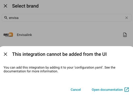
I modified the config locally before modifying my Home Assistance instance. An example is below:
# Example configuration.yaml entry
envisalink:
  host: 10.0.0.0
  panel_type: DSC
  user_name: user
  password: XXXXXXXXX
  code: "1234"
  port: 4025
  evl_version: 4
  keepalive_interval: 60
  zonedump_interval: 30
  timeout: 10
  panic_type: Police
  zones:
    1:
      name: "Door"
      type: "door"
    2:
      name: "Motion"
      type: "motion"
    3:
      name: "Window"
      type: "window"
  partitions:
    1:
      name: "Home Alarm"
In Unraid, I access the console for the Home Assistant container and used vi to add my config below the existing config. After restarting Home Assistant, I was able to see Envisalink in Integrations and all the sensors as entities. Plus an additonal entity for the keypad and another for changing the status of the system.
HomeKit Bridge
To connect to HomeKit, I searched "Apple" in the device to add and selected HomeKit Bridge. I then included the sensors, alarm control panel, and any other domains that seemed relevant.

I scanned the QR code provided through the setup to add the bridge to my home. The sensors were properly detected and I was able to arm and disarm. It registers any changes almost instantaneously.
Conclusion
Overall, the swap was pretty simple. The most difficult part was removing the panel box to add the additional mounting holes. Now I have better vision into my home's security and can possibly use the sensors in the future for automations like turning off the air condition if windows are open.


